A better title might have been: “The Compromised Dipole”.
Due to the limitations of the small residential lot I live on, I am no longer able to get anywhere near the proper height for my 130 foot dipole antenna. At the present time the ‘apex’ is a mere 6 feet or so above the roof line. This is why I refer to it as my “Compromise Dipole”.
There was a time I had it 50 feet above the roof line. Truth be told, I never used it much because it was a hassle to tune it and to change the amplifier settings. It also produced constant RFI problems, which discouraged my use of the lower HF bands for quite some time. However, as I made improvements to the shack (in terms of automation) the tuning hassles and amplifier settings were no longer an issue.
But the RFI was another story…Did I mention the shack is on the second floor?
I was experiencing terrible RFI problems in the shack and in other locations within the house. Any TX on 30m or below was a complete disaster. I was getting RF in all the PC’s in the shack, and several appliances in the house as well.
I realized it was time to get things in order with the dipole once and for all.
As I began planning for my recent remodeling of the shack, I added RFI mitigation to the list of things that required research. I needed to be able to operate at full output on every band without concern for RFI. It seemed like a daunting task at the time given my limited knowledge of the subject.
I decided to re-examine every aspect of how things had been connected previously. From the routing of the cables, to the physical separation of certain components, to my (less than adequate) station ground. It wasn’t long before I had developed a fairly comprehensive approach I was certain would resolve the problem once and for all.
It made no sense whatsoever to proceed with building the station if these issues were not completely resolved. So after some careful research I found a few documents that outlined exactly what needed to be done.
- Amateur Radio Station Grounding and Lightning Protection – by W5BWC
- Common Mode Chokes – by W1HIS
- Mosley Electronics MP-33N Docs
- Ferrite and Chokes by KF7P
My ‘take-away’s’:
From the grounding doc:
- Install a Low Impedance Ground
- Utilize Single Point Ground System
From the Choke docs:
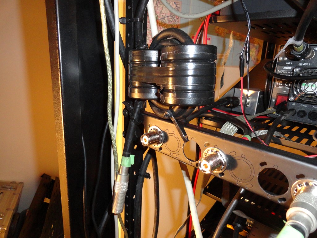
- Build a High Power W1HIS design RF Choke
- Install Clamp-On Ferrites on both ends of every cable
From the Mosley doc:
- Install a 5 turn coax choke at the feedpoint
From the KF7P website:
- Use “MIX 31” ferrite material
Results
I detail the actual installation of the grounding, chokes etc. in the Rack Mounting Project blog. Rather than rehash that here, let’s talk about the results.
Another key ingredient was the addition of the AT-AUTO antenna tuners. These tuners keep the SWR to an absolute minimum. Now that the linear amplifier is properly connected to a Low Impedance ground, it functions flawlessly. And finally, with the addition of the Mix 31 ferrites, the entire system is indeed much quieter. Noticeably quieter RX. And finally, all RFI has been eliminated.
There was no better proof of this than the performance achieved during this years CQWW WPX SSB contest. I operated on 80, 40, 20 and 15 meters, at full output, with no trace of RFI anywhere. No doubt the installation of the massive W1HIS choke was effort well spent.
In the end my “Compromise Dipole” at roof line elevation, did a surprisingly good job. I worked into South America, New Zealand, Japan, Hawaii, Europe, the Caribbean, and Canada on 40 and 80 meters. This dipole antenna has finally yielded some good use! (I call it a ‘zero to hero’ transformation)
I finally have a fully operational station. Fully automated, that can work on any band in any mode, at very low SWR, with quieter than the previous installation. More evidence of time and money well spent.