The decision was made to purchase the LG 32UD59-B 4K UHD monitor. It is scheduled for delivery on Friday (of course). This replaces the 46″ 1080p TV I was using previously. I will mount the new 4K monitor on the Ergotron Arm and position it above the dual 22″ displays, as before. I need to modify the dual monitor stand since the string/cable inside has snapped and it no longer supports any weight. I think I’ll just insert a block of wood or something to hold it up to the correct height and call it done. I also scored on a Palstar AT-AUTO.
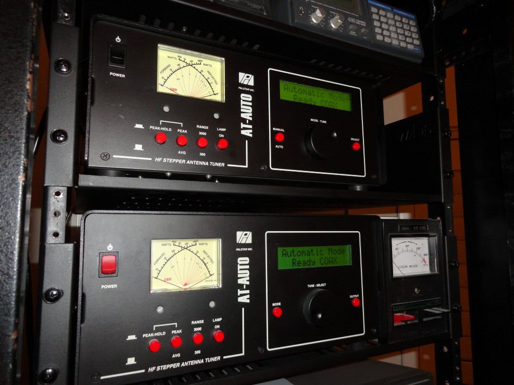
The other item I purchased today was a much sought after (second) Palstar AT-AUTO. I found one listed online and was lucky to get it after TWO previous ‘buyers’ backed out! The unit was serviced at Kessler and had upgrades installed, so I deemed it fair to pay a little more for this one than the first one I bought. No big deal. Now I have the two I need.
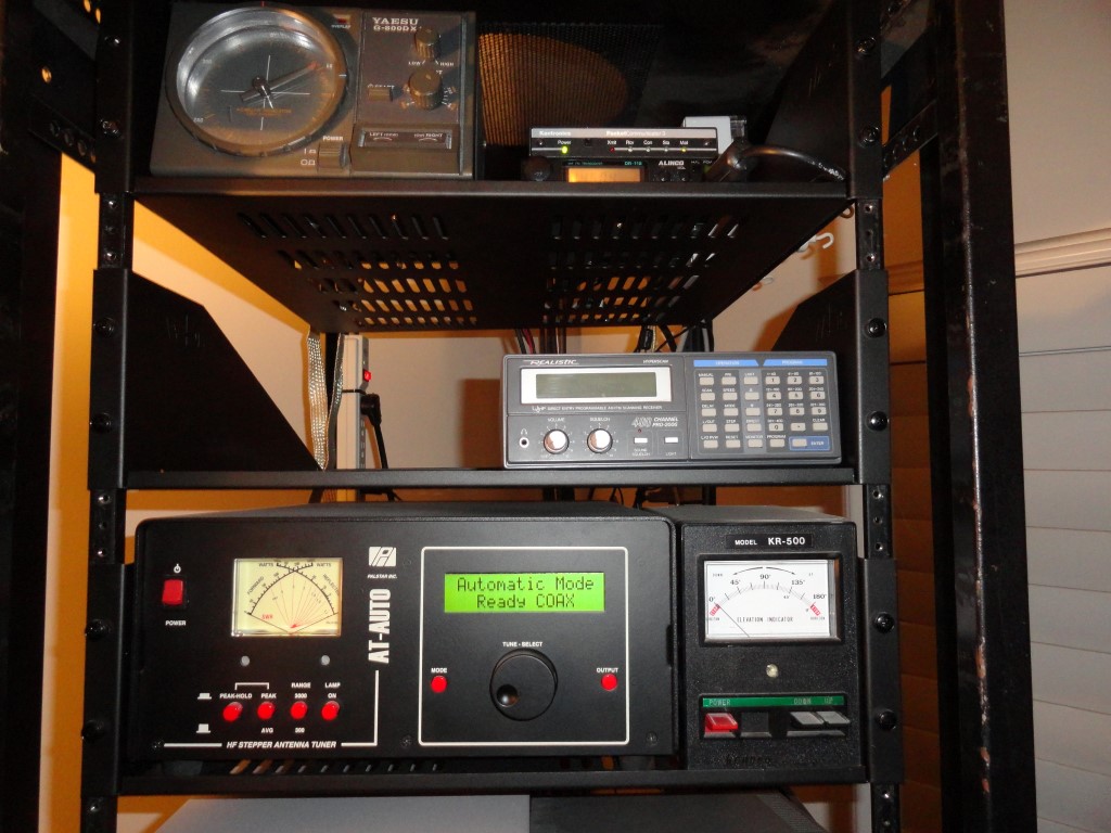
I’ll move that PRO 2006 scanner to the top shelf, under the Alinco data radio as originally planned, and install the AT-AUTO the same day it arrives. Tracking info to be made available tomorrow. Thanks to Robert KP4Y for what should be a very nice AT-AUTO. And…it has the same color buttons as my first unit.
The AT-AUTO is a fully automatic high power roller inductor tuner. No cranks to turn on this tuner! The AT-AUTO follows frequency changes in real-time when connected to the Flex 6000 series USB port. I consider the AT-AUTO to be one of the best auto tuners ever made. I just change to any frequency/band I please and the AT-AUTO typically delivers a 1.04:1 SWR. I no longer have to be concerned about SWR. The display is easy to read, and the tuner is quiet. The AT-AUTO does take some time to reach the tuned frequency when I switch to 160 meters, since the L and C settings for 160m are at the opposite end of the roller inductor. Other than that, the AT-AUTO typically tunes in a second or two once “trained”.
The tuner must be trained across all amateur bands so it can memorize the LC settings for your antenna. Since this unit was pre-owned, I will clear all memory before I retrain the tuner. To “train” the tuner, I transmit a tuning signal of 10w or so, and slowly tune from band edge to band edge on each of the amateur bands. The AT-AUTO stores all the LC settings in memory as you crawl each band. The AT-AUTO only has to tune, (or be trained) once. As long as you don’t change the antenna, the AT-AUTO recalls the stored settings for your current operating frequency, making tuning very fast. No worries about noisy relays, or arcing, due to its impeccable heavy duty design and construction
AT-AUTO – High Power, Heavy Duty, Fully Automatic, Computer Controlled, Delivering Near Perfect SWR.
From the Kessler Engineering website:
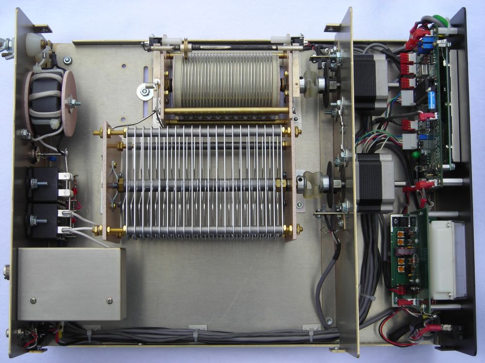
The AT-AUTO is a fully autonomous, fully automatic impedance matching network (an antenna tuner) that employs an embedded microprocessor to position a conventional roller inductor and a split-stator variable capacitor. It provides continuous coverage tuning from 1.8 – 54 MHz (including MARS, DoD, and commercial frequency bands, etc.) and is rated for 1500 W continuous carrier operation. The AT-AUTO is quiet and reliable, and with its industrial-rated stepper motors, provides a superior impedance match to that provided by the loud clanking boxes of relays provided by the competitors.
The Palstar AT-AUTO continuously measures forward and reflected RF power. As long as the SWR is below a user-selectable threshold, the AT-AUTO provides a “Good Match” cue in the Liquid Crystal Display (LCD) and takes no further action. Whenever the SWR exceeds the “Tune-Start” SWR, the AT-AUTO then counts the RF carrier frequency, looks up previously stored Inductor (L) and Capacitor (C) settings for the frequency of operation and then repositions L & C to the recalled settings. If the SWR is still excessive, the AT-AUTO automatically begins tuning, and provides user prompts during the entire process via the LCD. Once a good match is found, the new match settings are stored in memory for subsequent recall. The default behavior is highly customizable to suit individual needs.
The Palstar AT-AUTO is also able to obtain frequency information via the radio’s serial data port (for these compatible radios so equipped). By doing so, the AT-AUTO instantly follows frequency changes (VFO adjustment, etc.) and immediately recalls and sets the L & C for the new frequency – without the need to generate an RF carrier! The recalled match should provide an excellent SWR so that when RF is finally applied, subsequent tuning will not be necessary. While the serial port is not necessary for automatic tuning, this “Smart Mode” of operation greatly speeds the entire process of changing frequencies.
Note: The AT-AUTO is currently not in production and not available for sale. It is undergoing a redesign for release soon. The pictures and descriptions shown here are of the existing version(s) of the AT-AUTO tuner prior to its production cessation.
The Palstar AT-AUTO sends and receives serial data to/from the associated radio via the radio’s serial port. This is commonly referred to as Computer Aided Tuning or CAT. In order for the radio and the AT-AUTO to be able to communicate serially, an appropriate CAT cable must be used.
Because there is no defacto standard for CAT, there are variations in connectors and pin assignments from manufacturer to manufacturer. Therefore, there are unique AT-AUTO CAT cables for Elecraft, Kenwood, TenTec, Yaesu, and others. The CAT cables themselves are nearly identical, with minor variations in the specific connector and pin assignments.
ICOM has their own CAT implementation known as CI-V which uses entirely different protocols. ICOM radios, therefore, do not use the CAT cable, but instead use a CI-V cable.
Cable Sets consist of a Firmware Update Cable, A CAT/CI-V Cable, and in the case of some Kenwood radios, a Tuner-Handshake Cable. Schematic diagrams of the various cables are provided in the AT-AUTO user manual.