I was trying the FT8 digital mode for the first time on my new Flex 6500. The radio was in (full duty cycle) FT8 transmit at 100 watts into near perfect SWR when I heard a ‘pop’, after which, the radio would no longer power up.
I immediately assumed I had blown up the radio…
Yep, you could say I was a little ‘bent out of shape’. All I can say is, it’s a really terrible feeling. Mostly, I was angry at myself for having blown up the radio. Mega p1553d was more like it…
After regaining some composure, I noticed some of the other 12V gear, not in use at the time, was also off. So I pulled out the voltmeter, and sure enough (and much to my delight!) there was no DC on the power lead to the dead radio!
How Do You Spell Relief?
I immediately connected the radio directly to the power supply and started dancing when the radio powered up. RELIEF is not a strong enough word in this case.
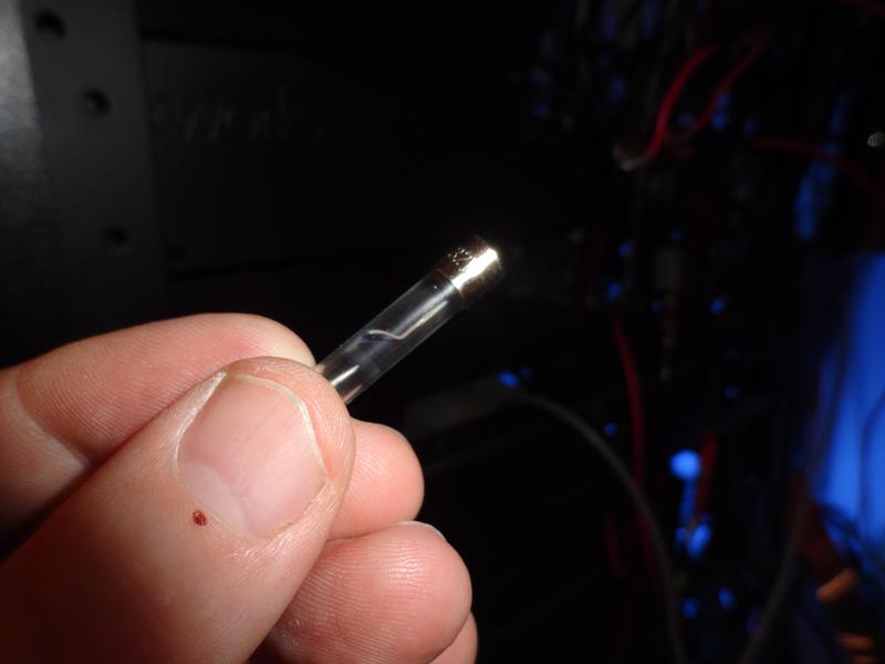
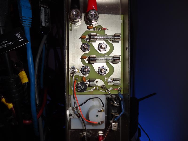
As it turned out, I had blown a fuse in the MFJ power strip!
The culprit: 15A 32V fuse
Can’t blame MFJ for this one! This is what happens when you try to draw 25A through a 15A circuit. A rookie mistake.
Easy to replace….If I can find one!
A couple of local stores are showing them in stock. This is a 15A/32v fuse.
In an effort to take some of the load off the MFJ-1118 I will connect the two 6000 series radios directly to the power supply. The MFJ-1118 is not relied upon to protect the radios, and I now realize that having it inline with the radios is wholly unnecessary.
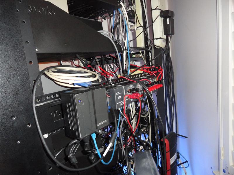
The most time consuming part of this problem was getting the power strip out of the rack! I had installed the MFJ power strip inside the rack behind the Flex 5000 and now realize it was a design flaw to have located it there.
After replacing the fuse, the MFJ-1118 will be mounted to the exterior side of the rack for easier access going forward.
OK, so by now, I’m sure you’ve figured out how I got myself into this situation!
In error, I had connected the Flex 6500 to a 15 amp circuit. While in full duty cycle transmit the radio requires 25 amps. Hence the pop!
I’ll replace the fuse, change my shorts, Hi Hi, and go on my way a little wiser.
UPDATE: Found the fuse at Home Depot, replaced the fuse and tie wrapped the MFJ-1118 to the side of the rack. Reconnected all the 12v gear, and everything is back together.
WSJT-X has arrived! I purchased the Flex 6500 for exclusive use in digital modes. I have the 6500 configured to listen for SSTV (Slow Scan Television) signals and EasyPal digital transmissions on the 20 meter band. At the same time I’m running two instances of wsjt-x on other bands.
Making Contacts via FT8
After following the set up instructions, and getting the audio and RF levels correctly set, I was making contacts via FT8 ‘right out of the box’. I’m running the Flex 6500 barefoot (100 watts) into a Comet CHA-250B multiband vertical antenna on a test stand in my backyard. The results were immediate. One of the first few contacts I made via FT8 was DX with JA0IXW. Not bad!
I have been able to complete almost every contact I’ve attempted so I’m pretty confident my little digital setup is working AOK! I’m putting out a very clean 100 watt signal.
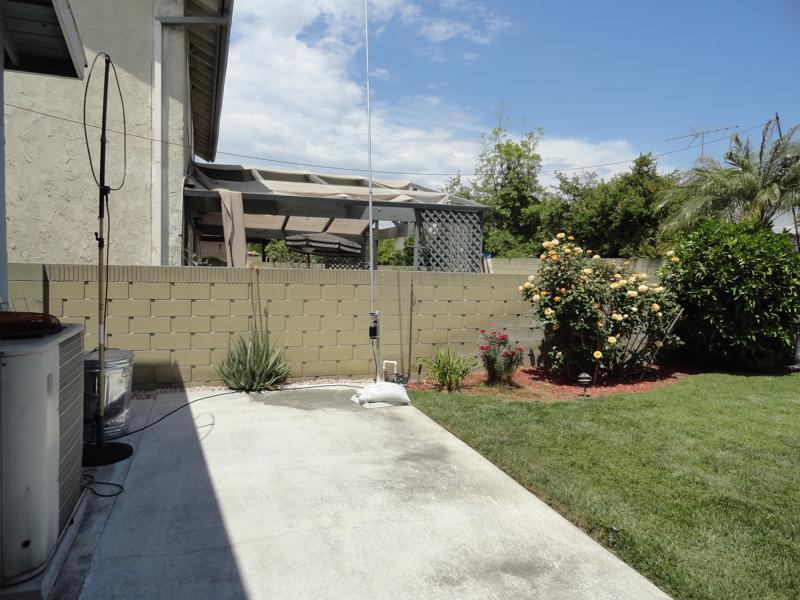
The Comet CHA-250BX vertical has been on the test stand long enough. It’s time to move it into a permanent location on the property.
Comet CHA-250B on the “test stand”
I plan to put the CHA-250BX on the top of one of the support masts that currently hold up one end of my “Height Compromised Dipole“. It’s in the corner behind a palm. I read a few eHam reviews that mentioned good results were achieved by mounting the CHA-250BX just 10 to 15ft above the ground. The antenna height affects the take-off angle, and apparently 10-15 feet is yielding some good results. I’m already working some DX barefoot via FT8, so I know the antenna performs OK. With all the testing, I now have a baseline to compare the performance against once it’s at the new height.
New Location For The CHA-250BX
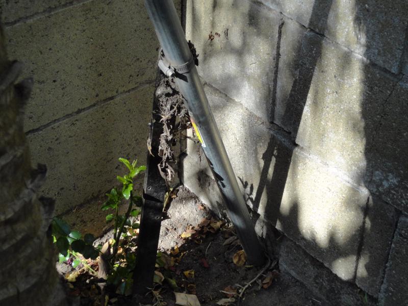
If you look closely at the image below you can see the mast in the corner of the yard. I had it strapped to a huge stake that I drove into the ground. It was held in place using hose clamps. It stood up straight for years until part of the palm died and knocked it loose. I’m going to extend the current 100ft Andrew CNT-400 with another 50ft of the same coax.
New Home For The CHA-250BX
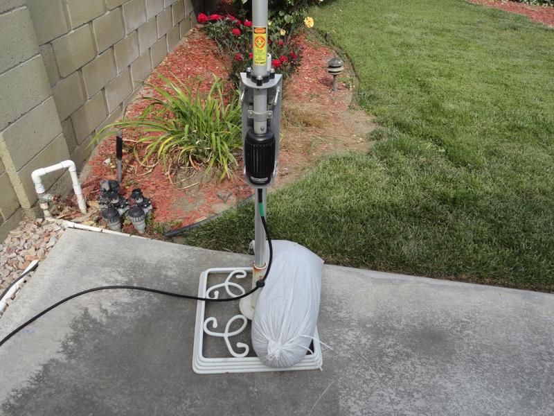
Recycle The Base Parts
The test stand is an old umbrella stand. I plan to fit the weighted base squarely into the corner against the cinder block wall, and secure it using the big stake, and the 50 lb sandbag.
Comet CHA-250BX Umbrella Base
This steel mast is 15ft tall, a 5 ft section on top of a 10 ft section. When I re-deploy the mast I will switch the 5 ft section to the bottom, this way, when I have the antenna ready to go I can stand on a step ladder and insert the 10 ft section much easier. If 15 feet is judged to be too tall to stabilize, I will eliminate the 5 foot section.
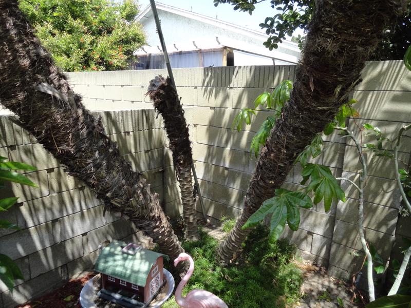
New Location For The CHA-250BX
Square In The Corner
The umbrella stand will fit perfectly into this corner.
I’ll re-use the stake to secure the stand
I have some mollies leftover from a recent flower trellis repair. I can use some of them as anchors for the steel straps if it looks like I’ll need them..
The Comet CHA-250BX will go into this corner
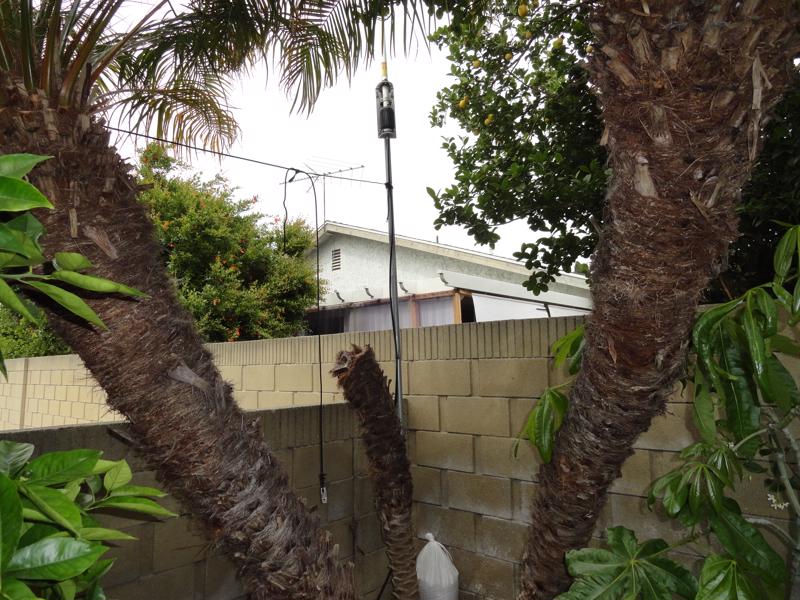
Comet CHA-250BX At Ideal Height
The 5 ft section will be reinforced using two sets of steel straps (at 1 and 5 feet above ground), and an additional guy line to reduce or eliminate any sway. I’ll add a pulley to the top for the dipole, and hang a weight from the end insulator to reduce stress on the mast when it’s windy. I’m also going to devise a wooden support beam that will go in between the mast and the 90 degree concrete corner. I’ll be able to tighten the steel straps to keep the mast firmly against the beam. I’ll square one end of the wooden beam for the corner, and make a cutout for the mast diameter on the other end. This should be a rock solid base. The antenna is 23.8 feet tall, and weighs 7 lbs. with a 67 mph wind rating.
I have a spare ground rod which I will install at the base.
Update: Sat 05/18/19
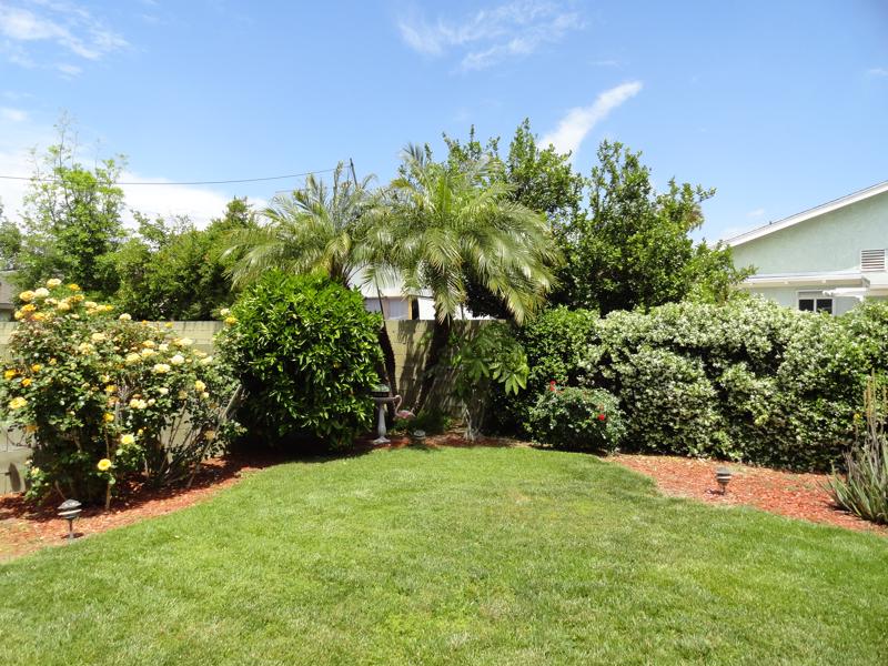
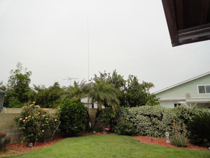
XYL: Where Did You Put That Antenna?
What Antenna?
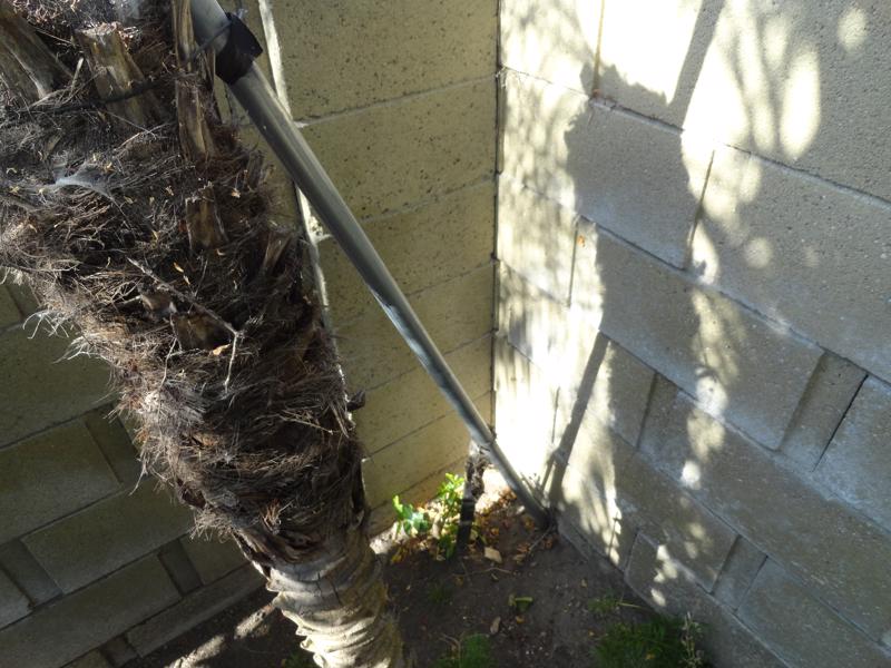
Where’s The Antenna?
Tucked away nicely in the corner of the yard! Barely noticeable to the XYL.
The feedpoint is now 3 meters above ground
There are several articles out there about antenna height versus take-off angle. There seemed to be some consensus that a height of 3 meters above ground offered some improvement in performance.
I decided the antenna would not be stable at the proposed height. Its proximity to neighbors property is also a factor. So instead of 15 feet, I mounted it at 10ft (3m)
OK. Let’s see what kind of results we get. The antenna had to move anyway, so hopefully we get some good results.
update: 05/20/19
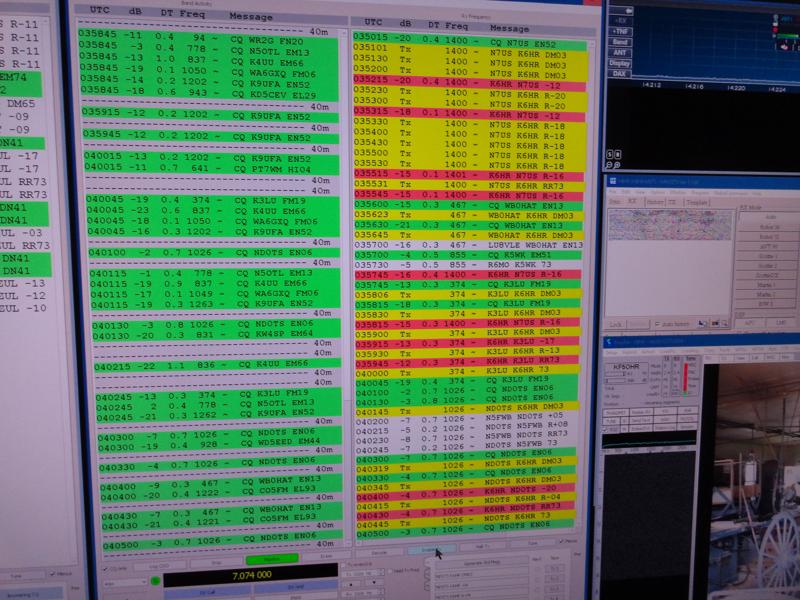
I leave two instances of WSJT-X FT8 running 24/7. Then, when I get home from work, I scroll back through the RX windows to see what was heard while I was away. I’ve been running it this way since I first put up the CHA-250 vertical back in March 2019.
INSTANT RESULTS
I’d left it on 40m since yesterday afternoon (just over 24 hours) and came home today to find EU callsigns in the FT8 console for the first time. Lots of DX calls, among them Italy, Croatia, Morocco, Mauritius, Ecuador, Japan, Indonesia, Philippines, New Zealand and on and on. Keep in mind this is just the past day on 40m! I never saw anything like this when the antenna was on the test stand.
If you have your CHA-250BX mounted on the ground give it a try on a 10ft mast! Let’s see how many of these newly heard DX callsigns can be worked!
the bonus: antenna separation
An added bonus! The increased antenna separation between the vertical and the RX Loop has eliminated the de-sense I was seeing on the 6700’s HF RX. As I work FT8 I am usually listening to 80m on the 6700/W6LVP Loop. The antenna separation is now sufficient that the FT8 transmissions no longer interfere with other HF RX in the shack. Perfect world.
it Turns out to be a major upgrade!
EA3KU 05/21/2019 05:15 FT8 100w 40M Sent -11 Rcvd -20
F6AOJ 05/25/19 04:28 FT8 100w 40M Sent -17 Rcvd -22
EA8TH 05/2519 06:23 FT8 100w 40M Sent -19 Rcvd -22
WSJT-X was installed on 03/09/19 and my DX contacts up to this point included JA’s and ZL’s and VK’s, but I hadn’t copied any EU callsigns before raising the antenna. Now I’m working into EU, so I am very pleased with this upgrade.
update 03/09/20 wsjt-x results
At this point, I’ve worked thousands of FT8 QSO’s and some great new DX. All you need is a 100 watt radio and this inexpensive antenna in order to work the world!
Time spent building the digital side of the station is proving to be time and effort well spent. The dedicated digital rig is paying off big time, as DX contacts are coming in on all bands. The DX results are better than anticipated!
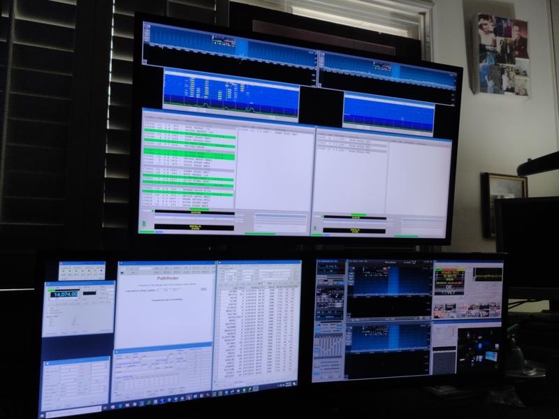
Flex 6500 – Four Slice Receivers: Two running WSJT-X, one running MMSSTV, and the fourth running EasyPal. Add a Comet CHA-250BX Vertical @ 10ft and that’s it!
Barefoot Digital: 100 Watts into a Vertical
I wanted this to be a simple barefoot operation with a dedicated radio and antenna. I’m using a Dell 7050 micro PC and have the Flex displays “cranked down” in order to limit CPU usage to a range of 40-60%. Works great!
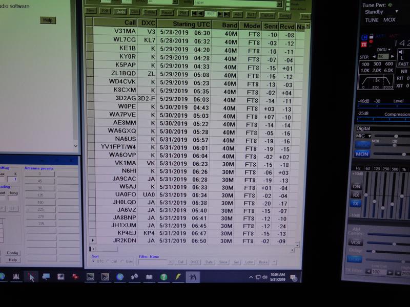
Evenings here have become a lot more interesting!
The past few evenings on 30 and 40 meters…See what I mean?
Every day this new digital mode attracts more and more people to the airwaves. It works with the briefest of openings and the software needed is free to download. It takes up about 60Hz only and works great with weak signals.
It has been 10 months since my first FT8 contact back on 2/15/19. Working HF barefoot in FT4 and FT8 modes. The dedicated Flex 6500 puts out about 86 watts into the CHA-250 vertical.
38 DXCC Entities and WAS
As of today 12/14/19 I’ve made 1,433 ‘FT’ contacts comprised of all 50 US States and the following DXCC entities:
Canada, Japan, Mexico, Spain, Cuba, Belize, Asiatic Russia, European Russia, Australia, Puerto Rico, New Zealand, Canary Islands, Venezuela, Fiji Islands, New Caledonia, Cayman Islands, Argentina, South Africa, Belgium, Ireland, Azores, Hawaii, Samoa, Mauritania, Alaska, Ecuador, Chile, Dominica, Costa Rica, Trinidad & Tobago, Aruba, South Cook Islands, El Salvador, Lesotho, France, San Andres Island, Columbia, and French Polynesia.
Nice Results for Part Time QRP OPS
I’m very pleased with the results I’m getting with the 6500 HF barefoot FT4 and FT8 operations. 1405 of the contacts are in FT8 and 28 so far in FT4. I installed WSJT-X v 2.1.2 on 11/28/19 and find that there is far less activity on FT4 than FT8. Nonetheless I will continue to work it as often as possible.
It will be interesting to see sometime down the line what kind of results I’ll get using the Mosley and the amplifier. The low power (QRP) operation is so much fun, I plan to keep it in place for the foreseeable future.
Perhaps a 2020 upgrade candidate to consider might be an amplifier for the Flex 6500…
WSJT-X implements communication protocols or “modes” called FT4, FT8, JT4, JT9, JT65, QRA64, ISCAT, MSK144, and WSPR, as well as one called Echo for detecting and measuring your own radio signals reflected from the Moon. These modes were all designed for making reliable, confirmed QSOs under extreme weak-signal conditions.