FlexRadio USB Cable Management
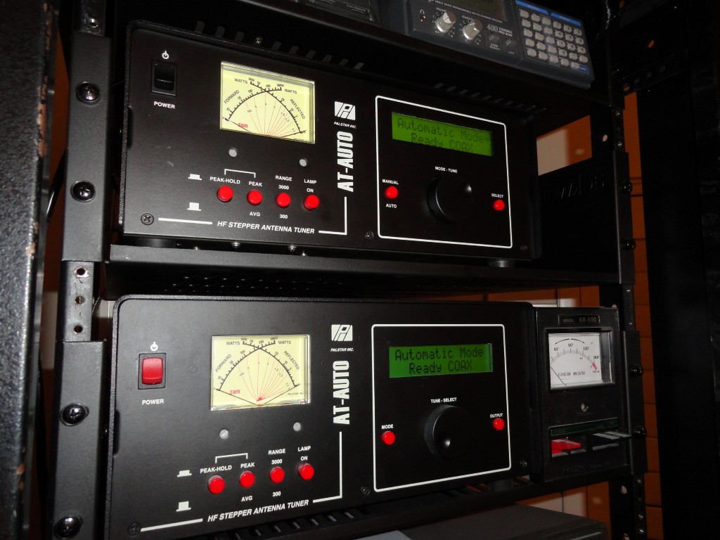
I control two Palstar AT-AUTO antenna tuners via the FlexRadio USB Cable Management function in SmartSDR.

The FTDI USB RS-232 cables supply frequency data to other serial devices in the shack directly from the transceiver. Very slick!
When I first installed the cables I took the default settings and connected the 9 pin end of the cable to the AT-AUTO serial port. It was Plug and Play! Just like that, I had the tuners following the radio! This meant I could click anywhere on any band, and my antenna would be tuned almost instantly, and, without the need to TX a tuning carrier! That’s right, once ‘trained’ the tuners arrive at their match position before I press the PTT button!
It was the ‘almost instantly’ bit that got me…
In other words, the antennas were tuning great, but they weren’t tuning efficiently. I’ll explain. (or perhaps you’ve guessed it already!)
I have two antennas:
ANT1 – Mosley TA33JR Yagi – For use on frequencies 14mhz and higher.
ANT2 – 130ft Dipole (Height Compromised) – For use below 14mhz.
Each antenna has a dedicated AT-AUTO.
I quickly realized that as I changed frequency and/or band, both tuners were tuning both antennas to the same frequency. No good, because this also meant that when I changed from a low band to a high band, (where the tuning presets are at opposite ends of the AT-AUTO’s range), both tuners had to travel the entire length of the tuning cycle! Really bad!
I didn’t make sense to operate this way, so I decided it was time to RTFM.
I needed the ability to assign one cable to each tuner and send independent frequency data to each tuner. If I could do this, then each of the two tuners could operate within the proper (close together) tuning range, and neither tuner would ever have to move very far to find a match, and certainly never have to travel the entire length of the tuner range again. Thus resulting in the ‘instant’ tuning I was looking for.
USB CAT Cable ‘Source’ selection
Much to my delight FlexRadio USB Cable Management allows you to select the source of the cables frequency data from a number of very useful sources!
The sources are:
- TX Slice – The cable will report the frequency of the slice receiver that holds the Transmit Indicator.
- Active Slice – The cable will report the frequency of the active slice receiver (the slice that has the yellow cursor)
- TX Panadapter – The cable will report the center frequency of the panadapter that contains the transmit slice
- Specific Slice – The cable will report the frequency of the specified slice (A, B, C, D, E, F, G, H)
- RX Antenna – The cable will report the frequency of the specified receive antenna (ANT1, ANT2, XVTR, RXA, RXB). Note: If multiple slices are on the same RX Antenna then the frequency of the last tuned slice will be reported.
- TX Antenna – The cable will report the frequency of the specified transmit antenna (ANT1, ANT2, XVTR). Note: This frequency is only changed/reported when the TX Slice is connected to the specified antenna.
Tremendous Versatility!
The Flex 6300 Transceiver only has one Spectral Capture Unit.
From the SmartSDR Documentation:
Because the notion of a receiver is firmly established in both the amateur community and possibly the rest of the world, it seemed inappropriate to describe the functionality of a wide-band sampling system simply as a “receiver”. Instead, in the SmartSDR world there are one or more “Spectral Capture Units”, or SCUs, that are responsible for the collection of wide-band data from the RF spectrum.
The SCU components are: an antenna input, an optional set of receive pre-selectors, and an analog-to-digital converter (ADC). Each SCU in the radio system can be connected to only one antenna at a time, but due to the sampling architecture it may support multiple receivers and spectrum displays.
The SCU enables listening to multiple bands at the same time on the same antenna. A hardware platform with multiple SCUs such as the FLEX-6600, FLEX-6600M and FLEX-6700 allows for monitoring multiple bands on different antennas or the ability to perform more complex noise mitigation techniques that are available in multi-antenna systems.
To operate the tuners independently and efficiently, and, having only one SCU to work with, I decided to source each tuners data utilizing the ‘Specific Slice’ source. I assigned the Mosley’s AT-AUTO to respond only to data from Slice ‘A’, and the AT-AUTO for the dipole to respond only to Slice ‘B’ data.
Going forward, for the 6300, I will simply use Slice A for all frequencies 14 mhz and higher, and Slice B for all frequencies below 14 mhz.
I’m really looking forward to the addition of the 6700 and the tremendous versatility I will have at my disposal.