New Years Day 2018 – Rack Mount Day

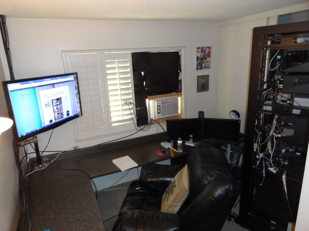
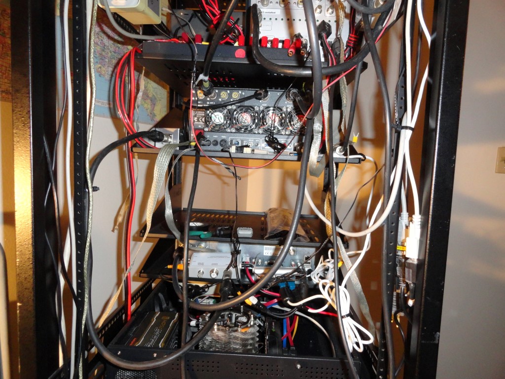
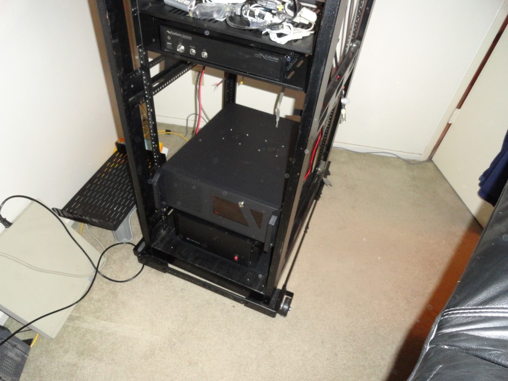
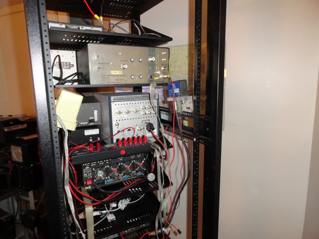
Here we go! The station is disassembled and most of the equipment is in the rack. I got a lot done today. Back to work tomorrow so progress will slow during the week. I was able to rack mount almost everything.

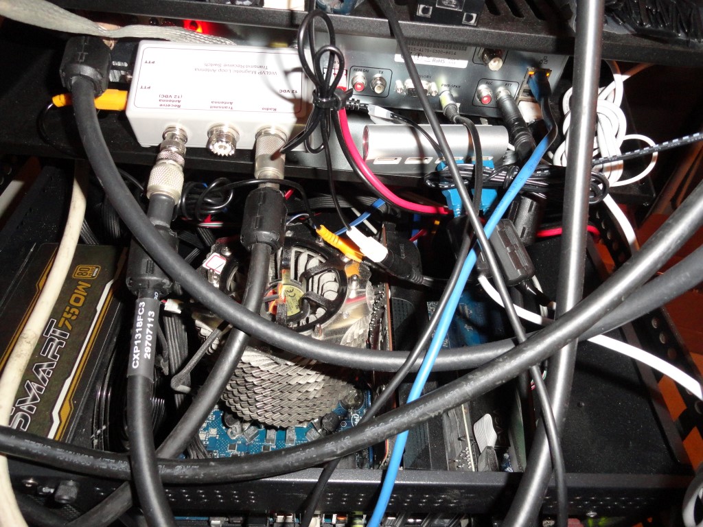
Now you can see why I needed to get moving on this. Whenever I needed to trace a cable back there it was virtually impossible. It was a rat’s nest, and, I could no longer reach behind the gear once I added the TV riser. This is what happens when you don’t have a walk space behind your desk. Even worse, every time I added gear, I would just overlay the cables in the back! Hence the rat’s nest.

Cabling rats nest
This is what it looked like behind the TV riser. Never again…

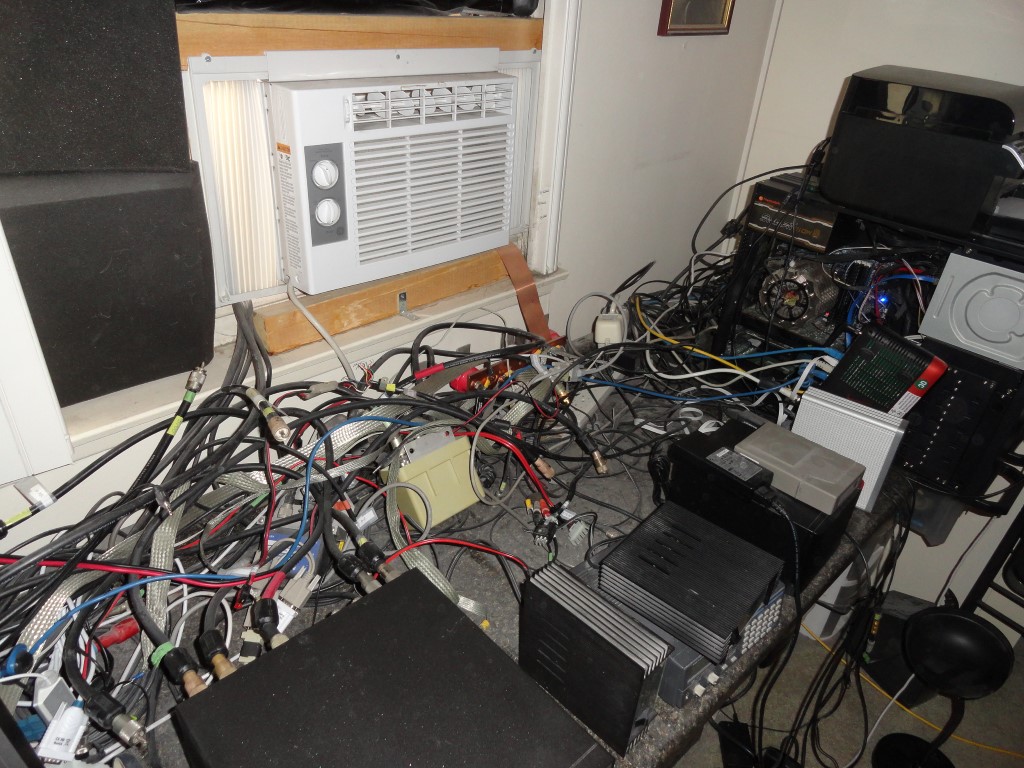
During my research for this remodel I looked at a lot of shack photos for ideas. Special thanks to Roger K7ERQ for the detailed desk plans and layout he sent me, that really got me thinking. All these great looking and functional shacks had one thing in common…They all had a walk space behind them. So I knew I had to have the ability to walk behind and work behind my gear, albeit for the first time after all these years!

The dust was unbelievable today. I was choking on the dust. Never again! The new shack will employ an oversized HEPA Filter. By the time I’m done, this room will be dust free, and stay that way thanks to the air purifier. I know, why didn’t I think of the HEPA filter sooner!

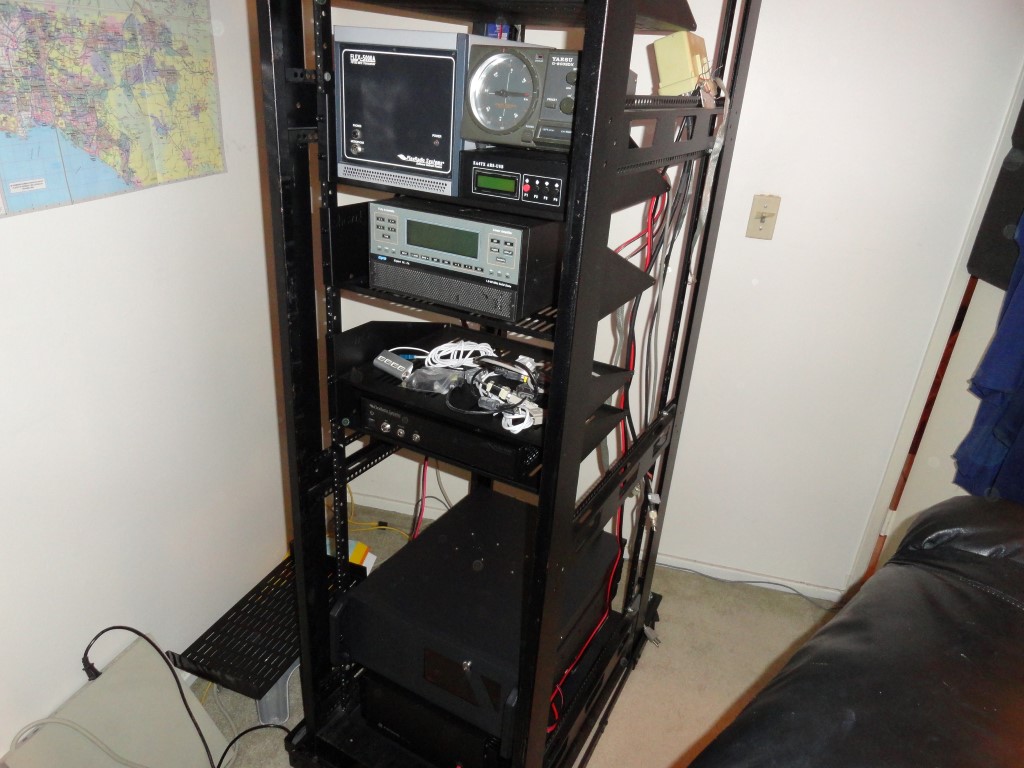
The Astron RS-70A power supply will have a PC mounted above it. The PC case is much deeper than the RS-70 which would have made it difficult to access the power supply. So, I came up with the idea to use this leftover cover from a PC to sit the power supply on.

Astron RS-70A
Makeshift sliding shelf for the Astron RS-70 Power supply

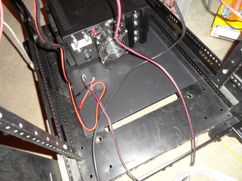
There’s enough clearance with the PC mounted above so I can slide the power supply forward or backward for service!

Astron RS-70A
The Windows 10 PC mounted above the Astron Power Supply is deep!

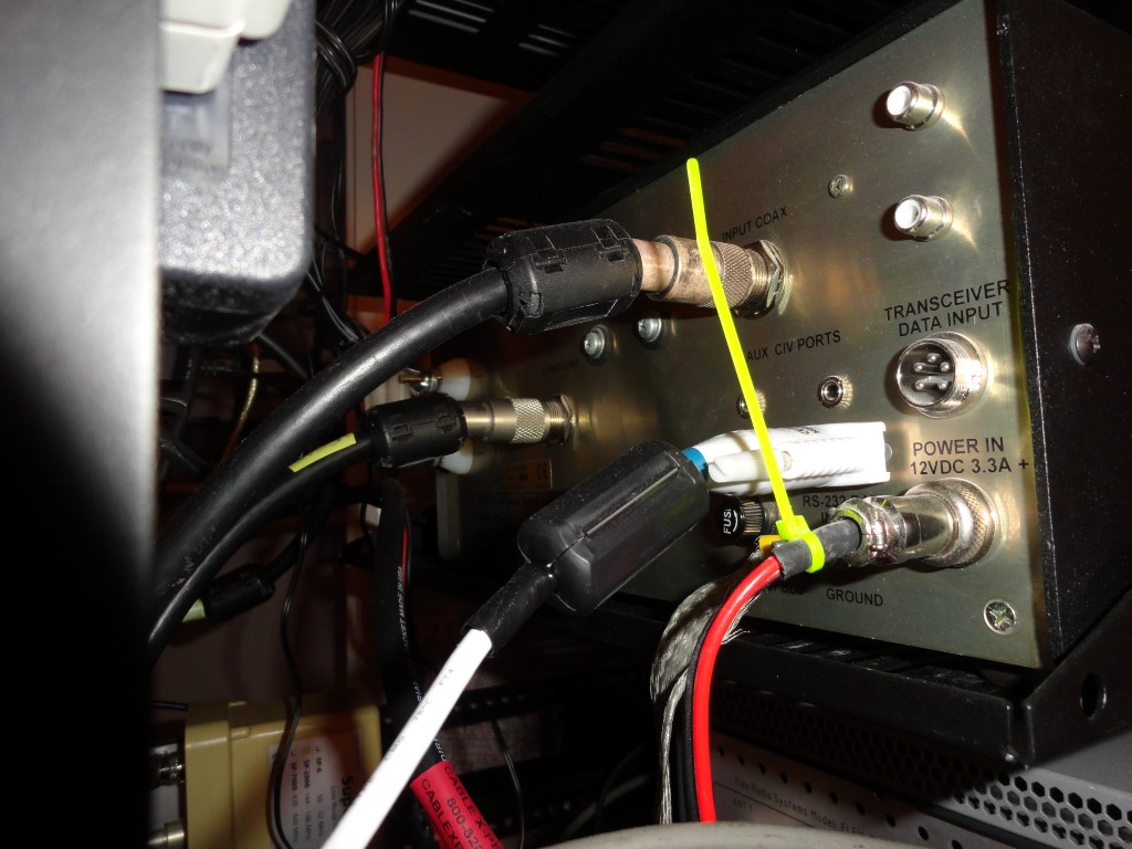
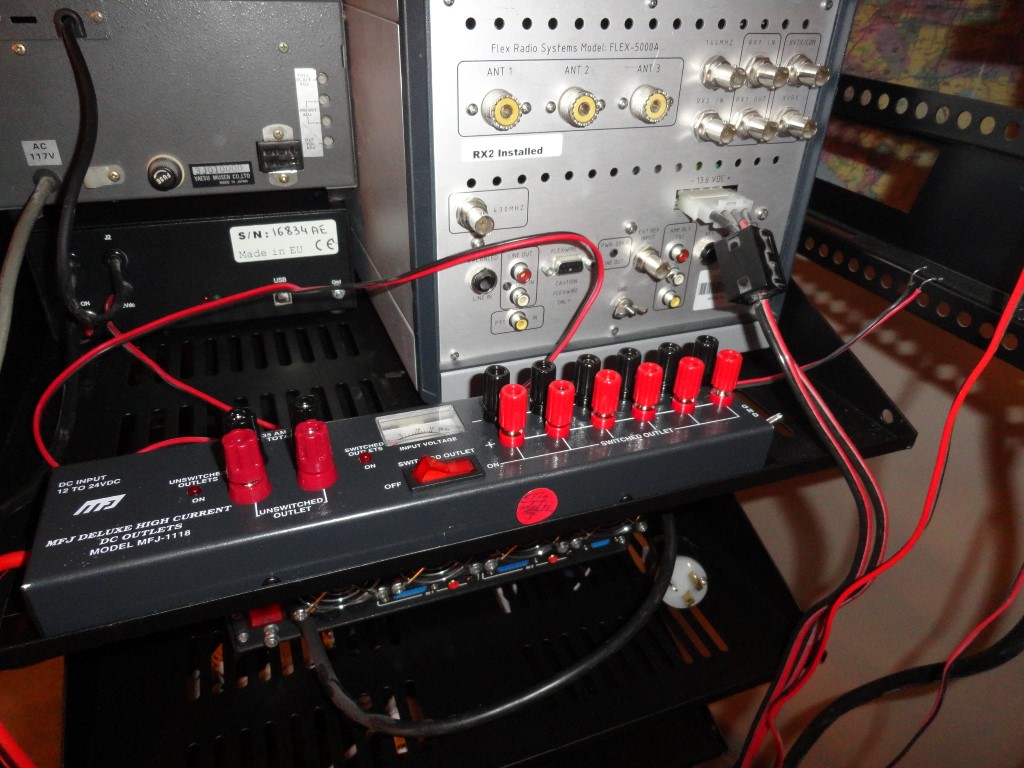
I connected the Flex 6300 directly to the power supply. I also connected an MFJ-1118 to get DC distribution to all the other components. I’m considering some of the Samlex power supplies to replace my aging RS supplies.

Astron RS-70A
Only two direct connections to the Astron RS-70A

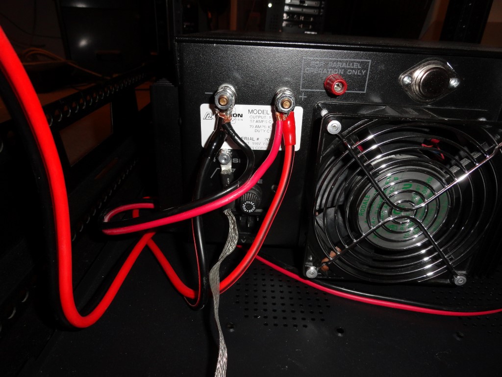
I’m connecting the Flex 5000 to the 35A terminals on the MFJ after discovering during planning that the 5000’s power lead would be too short to reach the RS-70 at the bottom of the rack. The 5000 only draws 25A max on TX, so the 35A DC distro panel was chosen. When I add the 6600/6700 radio later this year, it will also be connected directly to the power supply.

MFJ-1118
The Flex 5000 will connect to the 35A terminals on the MFJ DC Distro

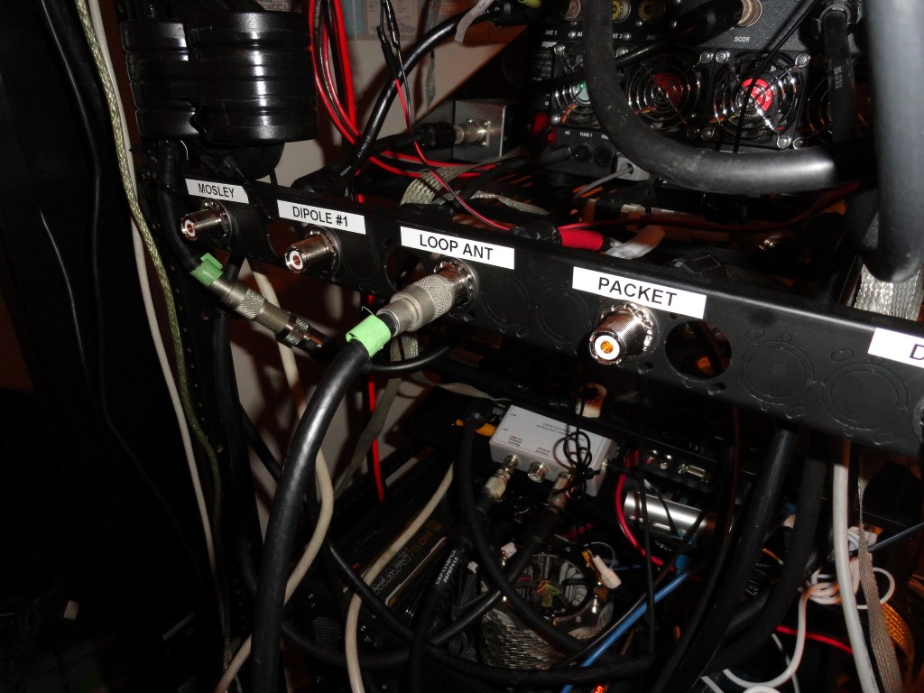
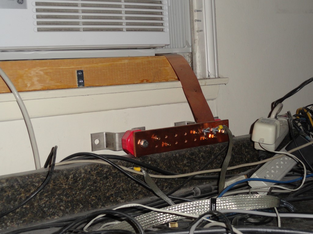
I also connected all the Single Point Ground leads. They will all tie to the station Grounding Bar which will be mounted on a rear pack panel when the project nears completion.

Georgia Copper
The Ground Bar will be mounted on a rear rack panel. The 2″ strap will be extended to meet the rack in the corner of the shack.
Single Point Ground
The Single Point Ground leads are also in place.

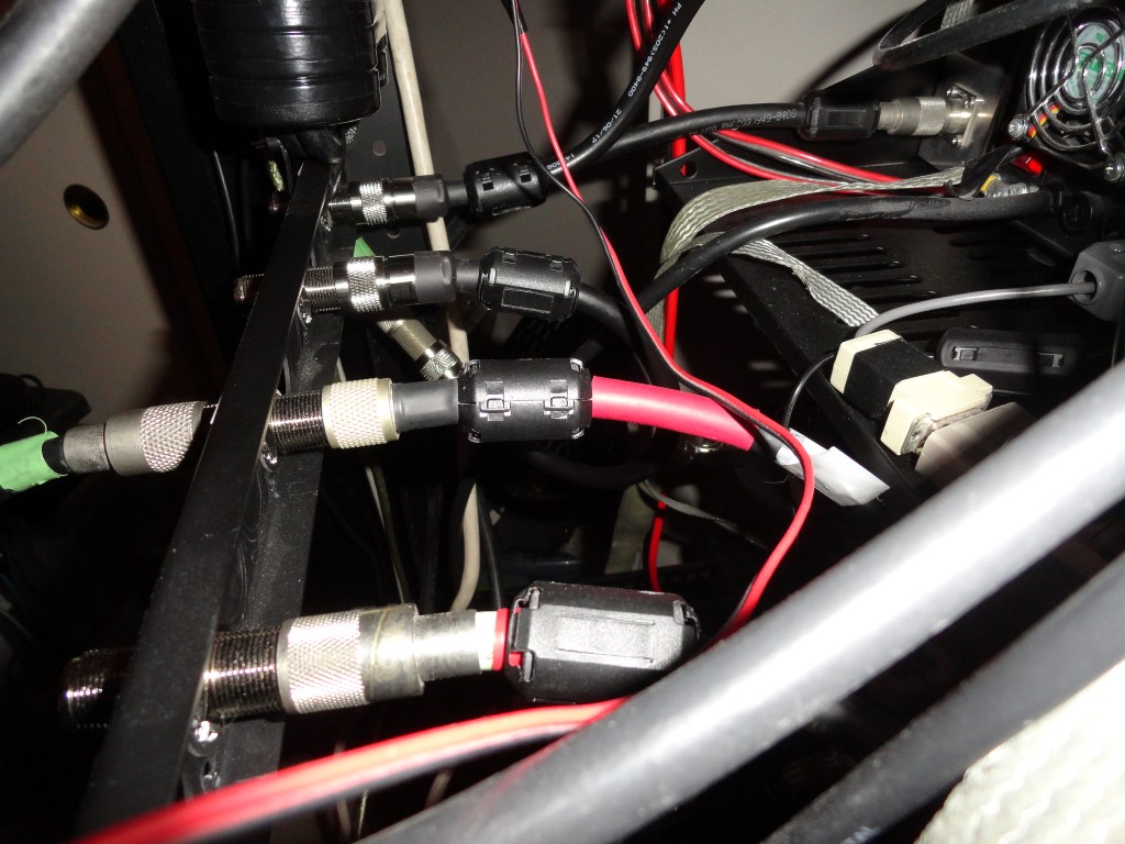
All the leads will be trimmed and dressed to make the wiring as clean and concise as possible. The complete opposite of what it was before. I also ordered sufficient numbers (and sizes) of Mix 31 Snap-On Ferrites. I will have proper fitting ferrite beads on both ends of every cable in the rack for RFI suppression.

Rack Mount everything
Good progress made today! The rack is getting heavy, but still rolls like a champ on the carpet!

I’ll continue wiring weeknights after dinner.

Back To The Front

Saturday Progress Report

I got started early today and got a lot accomplished. Here’s the Saturday progress report:

  • Placed parts order for 1ft jumpers (due 1/20)
  • Removed 4 monitors and cleared desktop
  • Cleared under desk area
  • Sorted all cabling, tools, and parts
Saturday progress report
Cleared the desktop!

At this point the rack is more or less electrically complete pending the installation of two more jumpers that are scheduled to arrive Tuesday. Initial testing shows everything is working as expected. Before I can move the rack into the TX test position (an area next to the desk where all the antenna coax cables can reach) I will have to split the desktop in the corner where the two pieces meet, and temporarily remove the section on the left along with the 46″ monitor and arm.

I currently have only the loop antenna connected as the antenna coax leads don’t reach the rack while it’s still in the ‘construction’ position. If all goes as planned I should be back on the air sometime next weekend.

What remains to be done:

  • Rearrange the antenna order on RF Panel #2
  • Install remaining jumpers
  • Install Secondary UPS Backup
  • Ground Bar and SPG leads
  • Satellite EL Rotor DB9 quick disconnect
  • AF output panel
  • Remove closet doors
  • Remove 46″ monitor and Ergotron Arm
  • Split desktop to accommodate rack
  • High Power testing
  • All remaining Snap-On ferrites
  • Reinstall all peripheral/office items

This wraps up the Saturday progress report

Back To The Front

RFI Battle! Choking Everything!

Choking everything! I’m still working through placing all the snap-on ferrite chokes. When complete, virtually every cable will have a proper fitting choke on each end. I plan to be choking everything. This really helps keep things quiet and eliminate RFI in the shack. In my previous setup I added ferrites one by one to eliminate problems, but couldn’t choke as many cables because I couldn’t reach half of them! In the rack it’s easy and I expect great results. The goal is to be RFI free at full RF output. Research showed you can never have too many ferrites. RFI suppression done right.

Labeled the antenna panel
Choking everything
All antenna leads have ferrite chokes on both ends
choking everything on at-auto
The business end of the AT-AUTO tuner
RFI suppression everywhere
The W6LVP Loop TX Switch will have a dummy load connected

The TX relay for the W6LVP Magnetic Loop Antenna will switch over to an MFJ-260C Dummy Load in the event the TX is engaged on “Radio #2” when the SPE 1K-FA is powered off. Better to be safe than sorry, even if only at tuning level output.

Both sides of the Array Solution Front End Protector are choked off also

Between the ferrite chokes and the Low Impedance Single Point Ground System the rack should perform quietly and be 100% RFI free. Of course there’s always the “Luck Of The Irish” so I won’t count my chickens just yet. High power testing this weekend!

Back To The Front

SO2R RX Loop Antenna

Todays work included installation of the SO2R RX Loop Antenna and associated devices. The W6LVP relay will provide switching for the SO2R RX Loop Antenna. I’ll also install some front end protection.

Here are some of the items on the agenda:

SO2R RX Loop Antenna
The wiring is nearly complete.

The SPE Expert 1K-FA amplifier allows connection of two transceivers, four antennas, and, an SO2R RX antenna. When the OP is transmitting on radio#1, radio #2 is connected to the SO2R RX antenna. This enables the operator to listen on radio #2 while working the latest DX on radio #1, and vice versa.

SO2R RX Loop Antenna for low noise

Operating in SO2R mode presents the possibility of overloading or damaging the sensitive RX front ends of the two connected transceivers. The 1K-FA manual warns of this possibility and cautions the user about antenna separation and it is suggested (and makes the most sense) that receiver front end protection devices be considered.

The Flex transceivers have built-in RX protection, but adding an RX front end protection circuit offers one more level of protection.

From the May 2014 QST article:

The RXFEP uses multiple devices to soft limit input signals starting at –1 dBm and outputting a specified maximum signal level of +10 dBm to the re-ceiver input.While manufacturers do not generally specify the maximum safe input levels for their equipment, it is worth noting that ARRL Lab re-ceiver dynamic range tests include input signals as high as +10 dBm, and we haven’t lost one yet.

An obvious place to install this device is at the RECEIVE ONLY ANTENNA port of a receiver. By having it as close to the receiver as possible, any pickup on the cable between the device and the receiver is minimized. There is another potential application in some installations, however. Some receive-only antennas include a remote preamplifier at the antenna termination. A protector at the remote preamp input would also be appropriate, although consideration should be given to the preamp input impedance, with a transformation to 50 W, if needed. If there is a long coax run from the remote preamp to the receiver, a second protector could be used at the receiver in case of loose coax connectors or other shield impairments. It should be obvious, but I’ll say it anyway. This unit cannot be used on any antenna feed that is also used for transmitting. Damage to both the unit and the transmitter would be likely consequences.

The low noise RX Loop Antenna is hereby considered a major station improvement!

Back To The Front