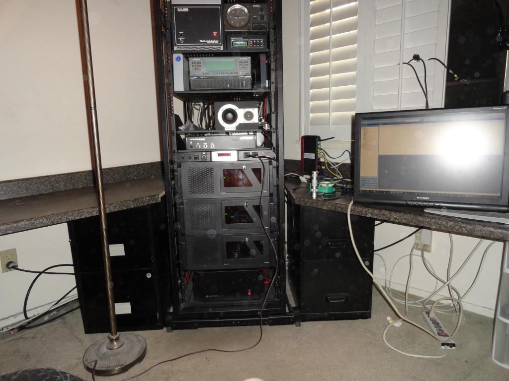
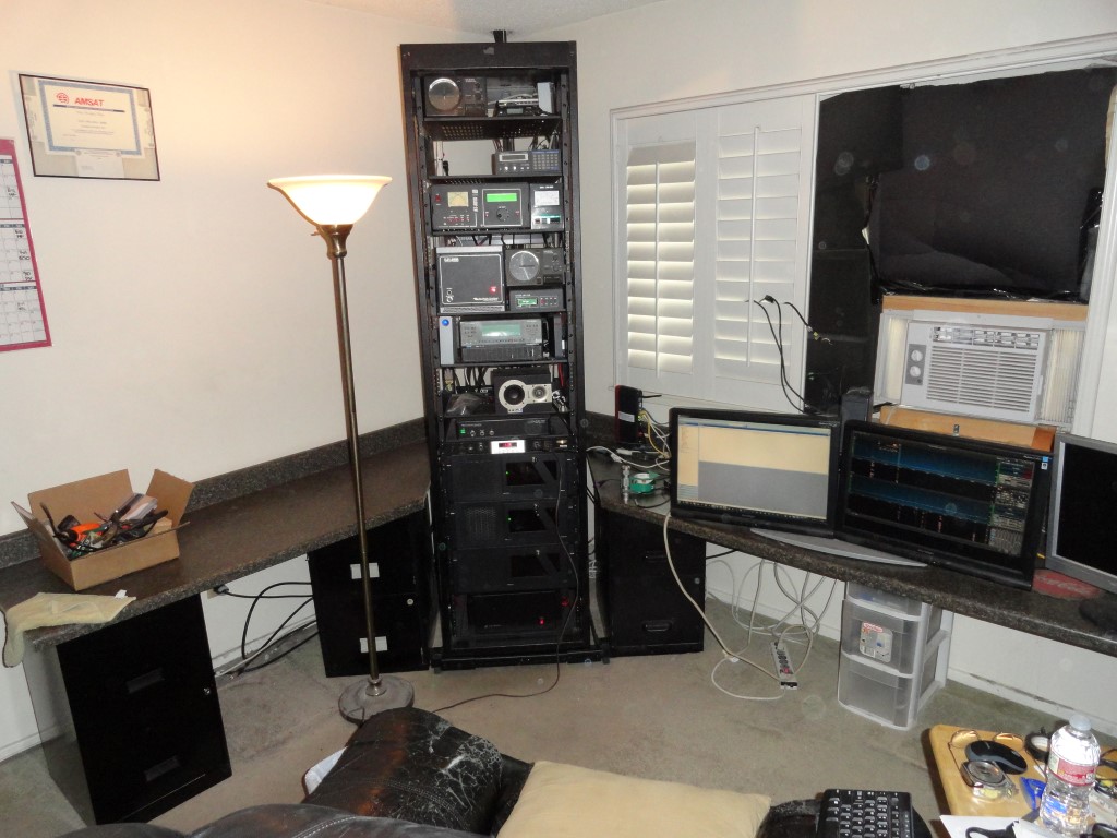
New Years Day 2018 – Rack Mount Day

Here we go! The station is disassembled and most of the equipment is in the rack. I got a lot done today. Back to work tomorrow so progress will slow during the week. I was able to rack mount almost everything.

Now you can see why I needed to get moving on this. Whenever I needed to trace a cable back there it was virtually impossible. It was a rat’s nest, and, I could no longer reach behind the gear once I added the TV riser. This is what happens when you don’t have a walk space behind your desk. Even worse, every time I added gear, I would just overlay the cables in the back! Hence the rat’s nest.
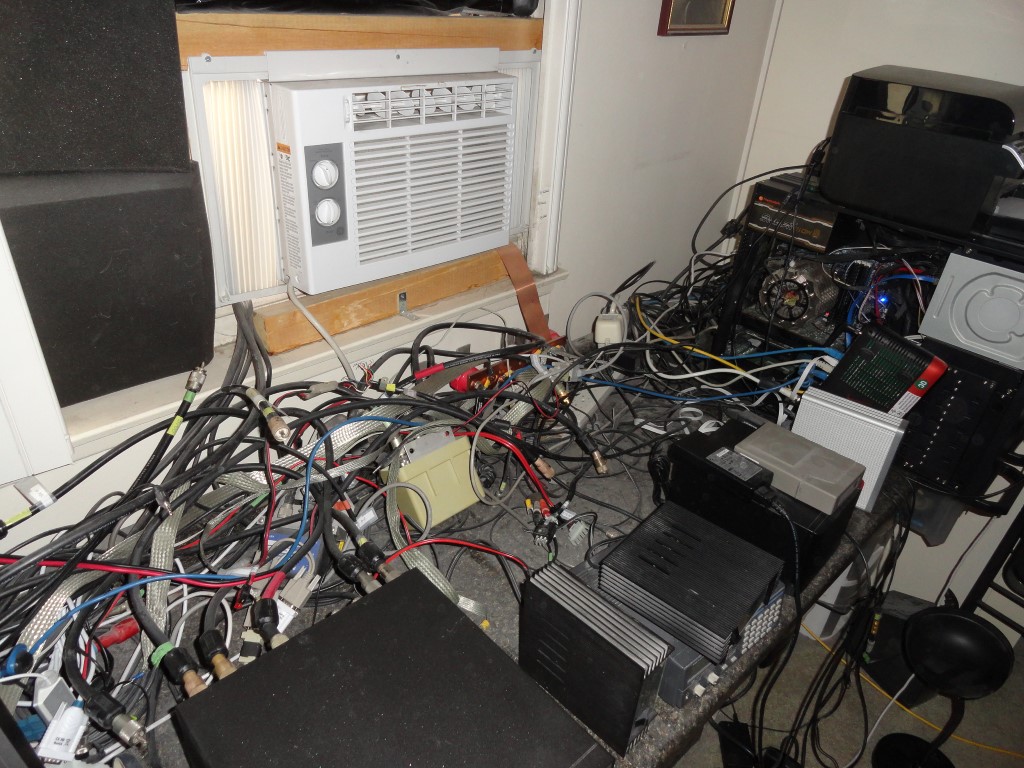
Cabling rats nest
This is what it looked like behind the TV riser. Never again…

During my research for this remodel I looked at a lot of shack photos for ideas. Special thanks to Roger K7ERQ for the detailed desk plans and layout he sent me, that really got me thinking. All these great looking and functional shacks had one thing in common…They all had a walk space behind them. So I knew I had to have the ability to walk behind and work behind my gear, albeit for the first time after all these years!

The dust was unbelievable today. I was choking on the dust. Never again! The new shack will employ an oversized HEPA Filter. By the time I’m done, this room will be dust free, and stay that way thanks to the air purifier. I know, why didn’t I think of the HEPA filter sooner!

The Astron RS-70A power supply will have a PC mounted above it. The PC case is much deeper than the RS-70 which would have made it difficult to access the power supply. So, I came up with the idea to use this leftover cover from a PC to sit the power supply on.
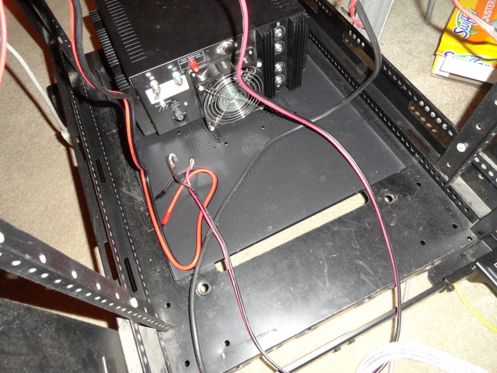
Astron RS-70A
Makeshift sliding shelf for the Astron RS-70 Power supply

There’s enough clearance with the PC mounted above so I can slide the power supply forward or backward for service!
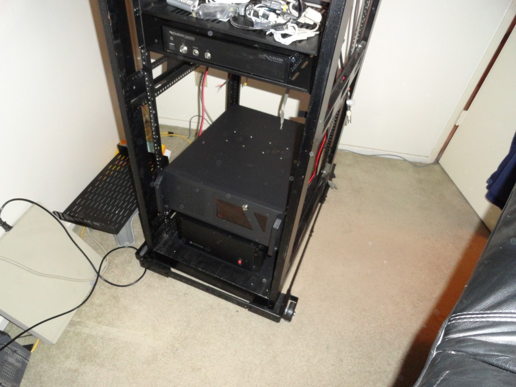
Astron RS-70A
The Windows 10 PC mounted above the Astron Power Supply is deep!

I connected the Flex 6300 directly to the power supply. I also connected an MFJ-1118 to get DC distribution to all the other components. I’m considering some of the Samlex power supplies to replace my aging RS supplies.
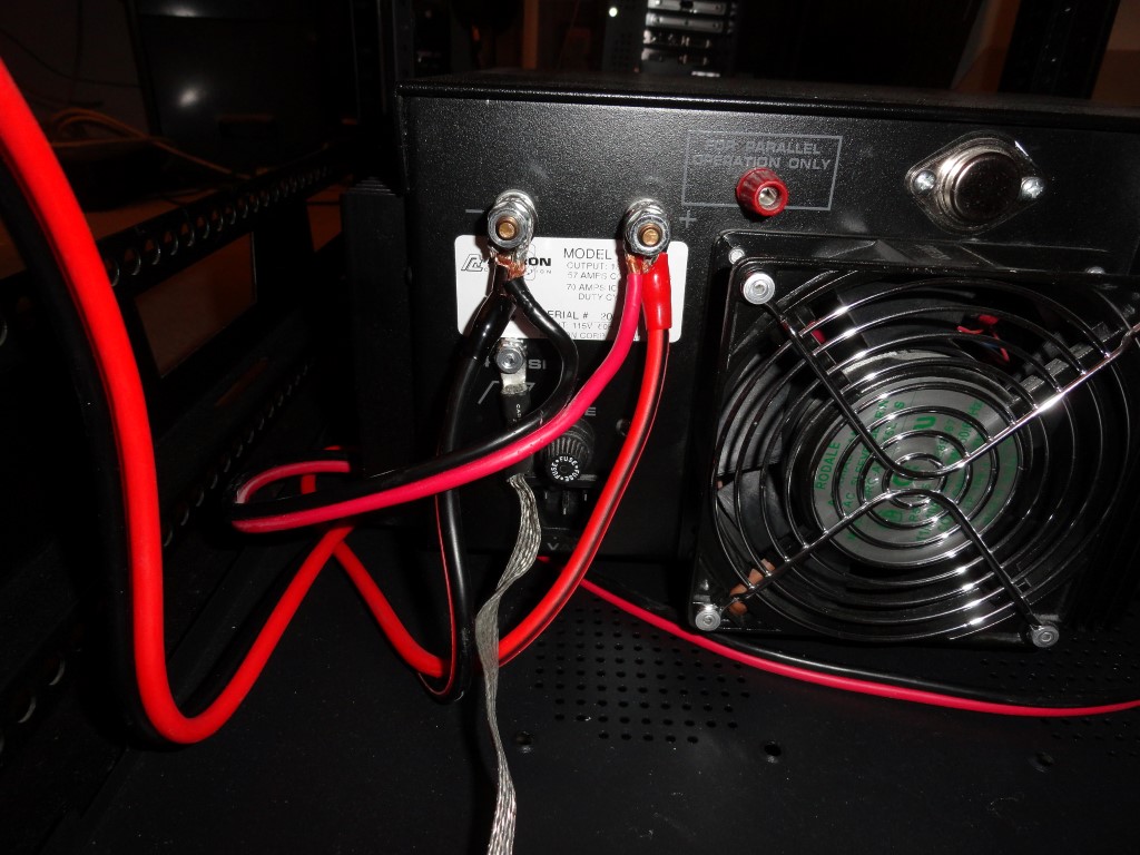
Astron RS-70A
Only two direct connections to the Astron RS-70A

I’m connecting the Flex 5000 to the 35A terminals on the MFJ after discovering during planning that the 5000’s power lead would be too short to reach the RS-70 at the bottom of the rack. The 5000 only draws 25A max on TX, so the 35A DC distro panel was chosen. When I add the 6600/6700 radio later this year, it will also be connected directly to the power supply.
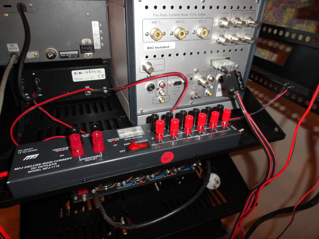
MFJ-1118
The Flex 5000 will connect to the 35A terminals on the MFJ DC Distro

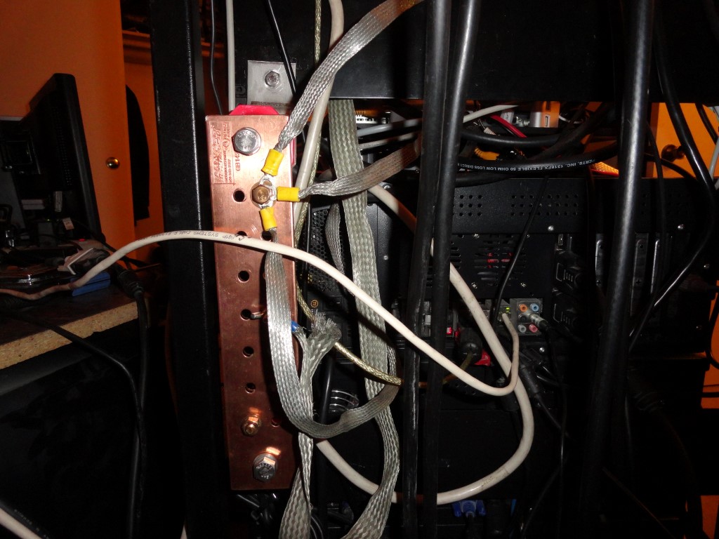
I also connected all the Single Point Ground leads. They will all tie to the station Grounding Bar which will be mounted on a rear pack panel when the project nears completion.
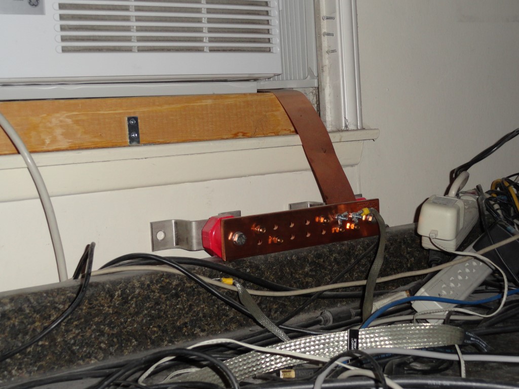
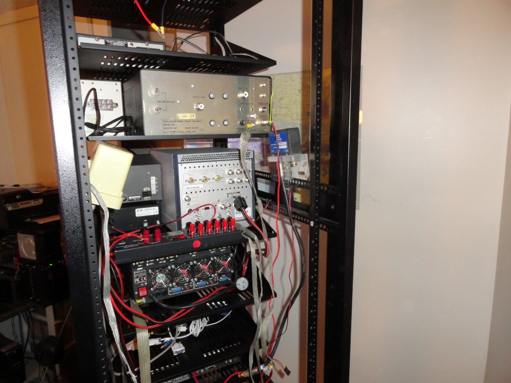
Georgia Copper
The Ground Bar will be mounted on a rear rack panel. The 2″ strap will be extended to meet the rack in the corner of the shack.
Single Point Ground
The Single Point Ground leads are also in place.

All the leads will be trimmed and dressed to make the wiring as clean and concise as possible. The complete opposite of what it was before. I also ordered sufficient numbers (and sizes) of Mix 31 Snap-On Ferrites. I will have proper fitting ferrite beads on both ends of every cable in the rack for RFI suppression.
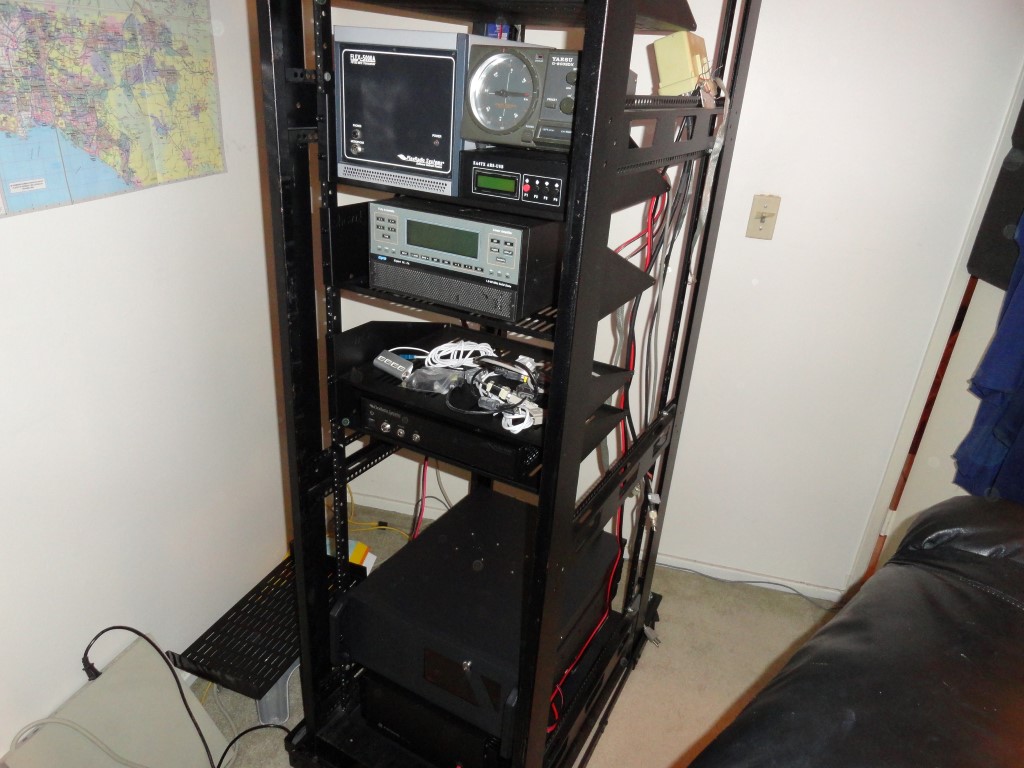
Rack Mount everything
Good progress made today! The rack is getting heavy, but still rolls like a champ on the carpet!

I’ll continue wiring weeknights after dinner.
Back To The Front

Amateur Radio Station Grounding – By the Book!

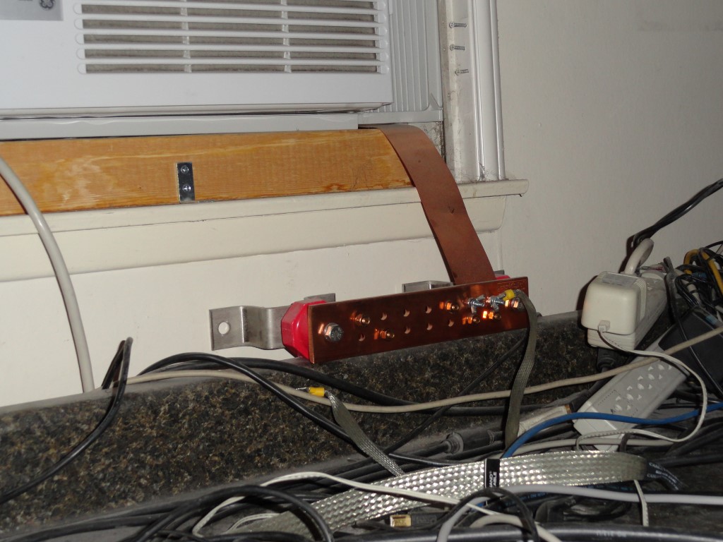
This weekend I will finish the ground bar ‘relocation’. The ground bar is currently located at the shack window .  Amateur Radio Station Grounding and RFI mitigation is of the utmost importance. My goal is to provide a low impedance earth ground to the rack. Here is another series of articles on station grounding that’s really worth reading. Read these two links! Highly recommended!

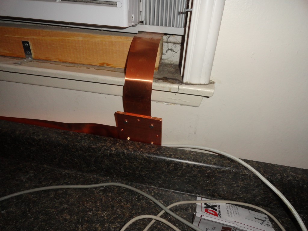
The HF station ground bar
This 2″ Copper Strap will extend along the wall to the rack.

Ground Bar Relocation

I plan to mount the ground bar vertically on the rear of the rack by bolting it to a couple of rack panels. The panels will serve as the foundation for mounting the ground bar at the correct height and  position to connect the 2″ strap that’s running along the wall to the rack. All equipment will connect to the ground bar, then the strap will be bolted to the bars with some strain relief (service loop)

Ground Bar mounted!
Ground Bar mounted!

To accomplish this I purchased a set of DXE-MSC-3 Copper Strap Bonding Clamps. The clamps will allow me to make a 90 degree turn to the left under the window, and run another piece of 2″ strap along the wall (behind the countertop). I’ll leave a “service loop” of strap in the back of the rack long enough, that I can pull the rack out for service without having to disconnect the strap. W5BWC’s article should be required reading for all amateurs who own and operate an HF station. Amateur Radio Station Grounding is just as important as the antenna!

2" Copper Strap 90 degree turn!
2 inch Copper Strap left turn!

Securing The Ground Strap

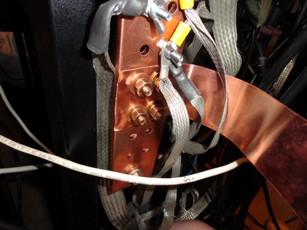
Securing the loop was easier than expected. I had concerns about the loop and attaching it to the bar. Problem solved…

Low Impedance HF Station Ground
That’s a solid ground connection!

I traced through the holes in the bar with a paper and pencil, and created a drilling template for the end of the strap. Four 3/8″ holes perfectly lined up. Ground Bar done! At some point I’ll attach the strap along the back of the countertop so it’s not just hanging loose back there.

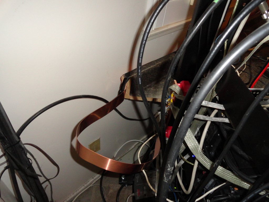
Copper strap service loop
2″ copper strap loop so I can pull the rack forward for service.

Finally A Solid Ground!

The plan worked out great! I was able to push the rack all the way back into the corner, and there’s enough ‘slack’, that when needed, I can pull the rack out far enough to sit/stand behind it. This is exactly how this was planned, and I’m pretty happy with it right now.

Radio Rack and temporary desktop
With the desktops temporarily back in place.

I can start measuring for the finishing touches, including the addition of a 32″ 4K UHD monitor. I’m currently considering the Samsung U32H850. If it fits, this is most likely the monitor I will use to replace the 1080p TV in my previous shack setup.

Th station is beginning to shape up
The shack is finally starting to shape up! Yeah, I know, I’ll switch the file cabinet on the left so the handle colors match on either side of the rack!

Now that everything is grounded, I’ve started testing with RF. I found a couple of wiring errors to the amplifier that are now corrected. Key down at half power (600w) showed no evidence of any RF in the shack. I’ll try some full output tests tomorrow. Yeah! I finally took down that ratty looking YAESU Wall Map!

Remaining To-Do List

The ‘still to do’ list:

  • Relocate AC power distro
  • Relocate Router and Printer
  • Measure for use of TV riser
  • Measure for relocation of Ergotron Arm
  • Measure for 4K UHD monitor
  • Reconnect Scanner Audio
  • Reconnect Satellite Rotors
  • Reconnect NAS

After full power testing is complete, I will not do any more work on, or make any changes to the radio rack until after the ARRL International DX Contest (SSB) the first weekend of March. Radio work will resume after the contest. In the meantime I will get the ergonomic work going. The right side of the desktop can be completed. The left side must be done last, since access to the rack depends on sliding the left desktop out of the way.

It was money well spent on all the snap-on ferrites and on the extension of the 2″ copper strap. Initial testing shows everything is quiet and no RFI. I have a solid, low impedance, single point ground system in place. High power testing should prove the effectiveness of my Amateur Radio Station Grounding!

We’ll see how it goes at 1KW output…

Back To The Front