Ergonomic Layout

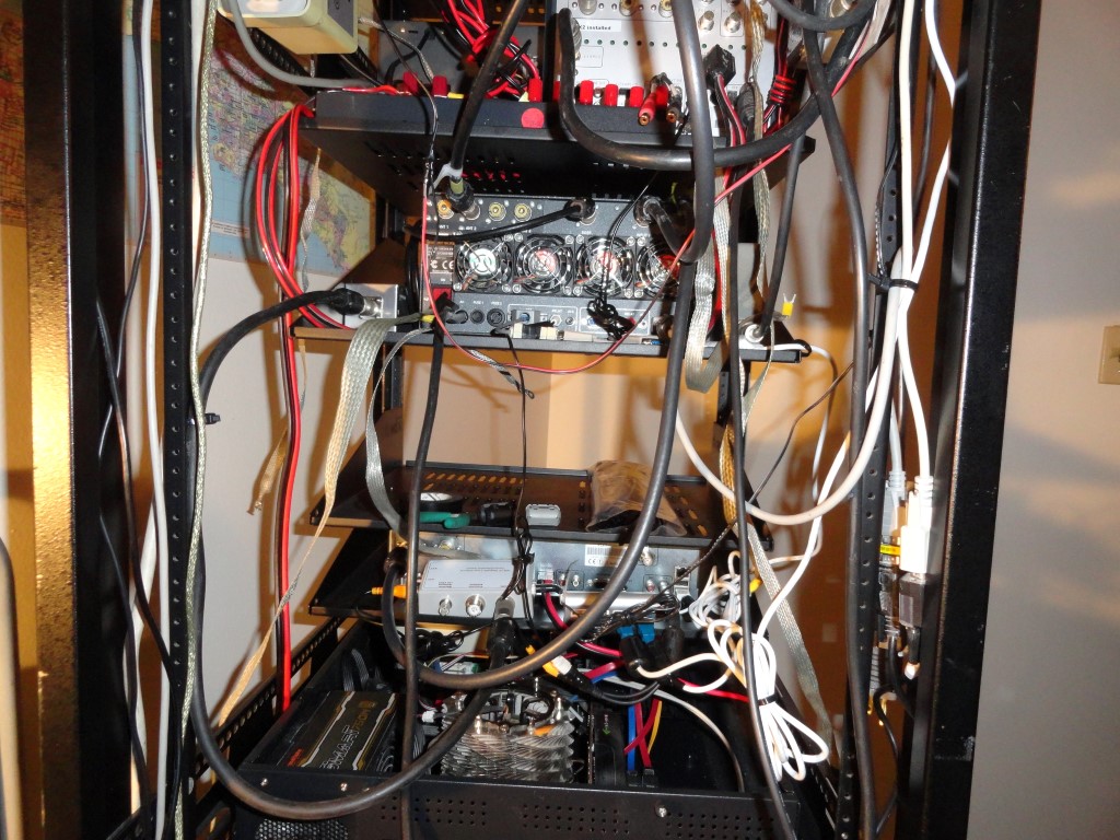
I have just enough space to rackmount everything. Considering I also have rear rack rails, some less important items can be mounted from the rear. This is all about the ergonomic layout. I may even build some breakout panels for the antenna and audio connectors. I’ll be using a combination of 2U and 3U rack shelves (special thanks to the folks at Gator Rackworks!)  I had to go 3U for some shelves in order to get a useable depth. Most of the radio gear will sit on shelves.

The current layout plan (from top to bottom):

  • ROTOR SHELF       4U
  • AT-AUTO HI           4U
  • AT-AUTO LO           4U
  • 2M RADIO / TNC   1U
  • FLEX VU5K            6U
  • 1K-FA                      4U
  • FLEX 6300             2U
  • FLEX 6700             2U
  • AC POWER             1U
  • PC#1 W7                4U  <<< DESKTOP
  • PC#2 W10              4U
  • PC#3 SERVER        4U
  • ASTRON RS-70      4U

I need the radios and amplifier close to the desktop, placing other ‘less touched’ items either down below or up above. I think the ergonomics are OK at this point.

Before I can start building I have to empty the shack so I can remove all the dust. I have a significant dust problem. And the problem was most apparent as I swapped out the cases on the two production PC’s. Choking on dust.

The plan is to empty the room, and mitigate the dust. I plan to use an air compressor to blow off the dust that’s embedded in the stucco-like ceiling, then, I’ll thoroughly vacuum before having the carpet steam cleaned. Going forward I will employ an oversized HEPA filter in the radio room which will run 24/7 to capture all particulates and hopefully eliminate or at least vastly improve my dust problem.
Back To The Front

SO2R RX Loop Antenna

Todays work included installation of the SO2R RX Loop Antenna and associated devices. The W6LVP relay will provide switching for the SO2R RX Loop Antenna. I’ll also install some front end protection.

Here are some of the items on the agenda:

SO2R RX Loop Antenna
The wiring is nearly complete.

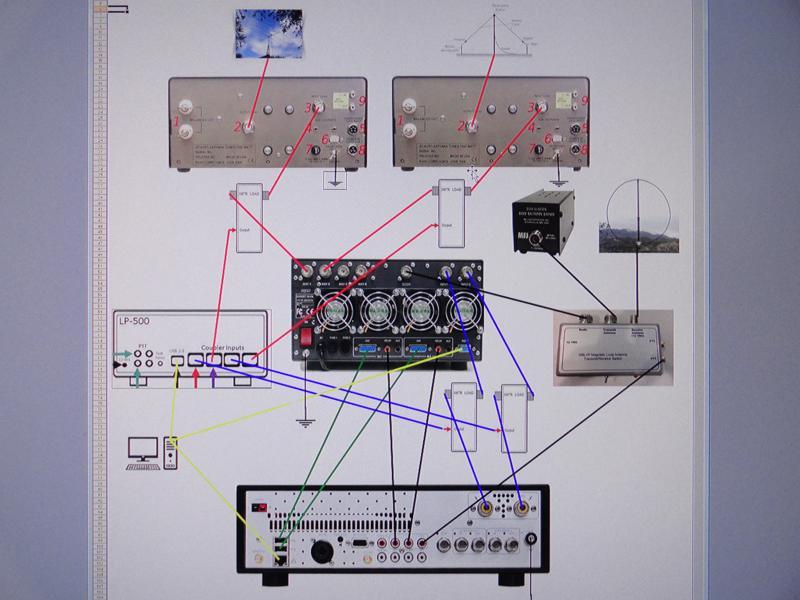
The SPE Expert 1K-FA amplifier allows connection of two transceivers, four antennas, and, an SO2R RX antenna. When the OP is transmitting on radio#1, radio #2 is connected to the SO2R RX antenna. This enables the operator to listen on radio #2 while working the latest DX on radio #1, and vice versa.

SO2R RX Loop Antenna for low noise

Operating in SO2R mode presents the possibility of overloading or damaging the sensitive RX front ends of the two connected transceivers. The 1K-FA manual warns of this possibility and cautions the user about antenna separation and it is suggested (and makes the most sense) that receiver front end protection devices be considered.

The Flex transceivers have built-in RX protection, but adding an RX front end protection circuit offers one more level of protection.

From the May 2014 QST article:

The RXFEP uses multiple devices to soft limit input signals starting at –1 dBm and outputting a specified maximum signal level of +10 dBm to the re-ceiver input.While manufacturers do not generally specify the maximum safe input levels for their equipment, it is worth noting that ARRL Lab re-ceiver dynamic range tests include input signals as high as +10 dBm, and we haven’t lost one yet.

An obvious place to install this device is at the RECEIVE ONLY ANTENNA port of a receiver. By having it as close to the receiver as possible, any pickup on the cable between the device and the receiver is minimized. There is another potential application in some installations, however. Some receive-only antennas include a remote preamplifier at the antenna termination. A protector at the remote preamp input would also be appropriate, although consideration should be given to the preamp input impedance, with a transformation to 50 W, if needed. If there is a long coax run from the remote preamp to the receiver, a second protector could be used at the receiver in case of loose coax connectors or other shield impairments. It should be obvious, but I’ll say it anyway. This unit cannot be used on any antenna feed that is also used for transmitting. Damage to both the unit and the transmitter would be likely consequences.

The low noise RX Loop Antenna is hereby considered a major station improvement!

Back To The Front

K6HR Contest Station Block Diagram

SO2R HF Contest Station Configuration

K6HR Block Diagram
K6HR HF Contest Station Block Diagram

Expert 1K-FA: At the Center of SO2R Ops

The Expert 1K-FA does all the antenna switching automatically. Fully automated, and carefully programmed, the 1K-FA greatly reduces the chance of user error. The K6HR Contest Station Block Diagram makes this SO2R setup a bit easier to understand.

The transceiver is a FlexRadio 6700 featuring two Spectral Capture Units. I utilize the two SCU’s as “two radios”, each with its own amplifier, tuner, and antenna. I designate ANT1 as the Mosley TA-33-JR-NW (for all HF bands 20 meters and above) and ANT2 as my 130ft Height Compromised HF Dipole for frequencies on 30 down thru 160 meters. Low SWR across all amateur bands!

The cool trick is the operator can move freely through the bands and operate at will via either radio. The 1K-FA’s foolproof switching ensures the TX radio will get the correct TX antenna every time. The second radio, in every case will be connected to the wideband RX loop antenna.

Data Driven via Flex USB

The Expert 1K-FA and the Palstar autotuners operate based on frequency data received from the radio. The 1K-FA and the AT-AUTO autotuners follow the radio in realtime as the operator changes frequency.

The operator only needs to turn the ‘tuning dial’ and press the PTT!

LP-500 Station Monitor

I have installed the LP-500 station monitor with 4 sensors. You could say it takes the guesswork out of getting good reports!

LP-500
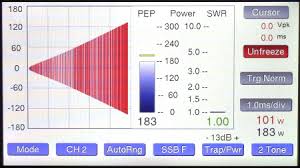
LP-500 Linearity Check

Leveraging the four sensors of the LP-500 Digital Station Monitor, I can ensure both amplifier channels are operating at full output, with the lowest SWR, and best linearity at all times.

Back To The Front