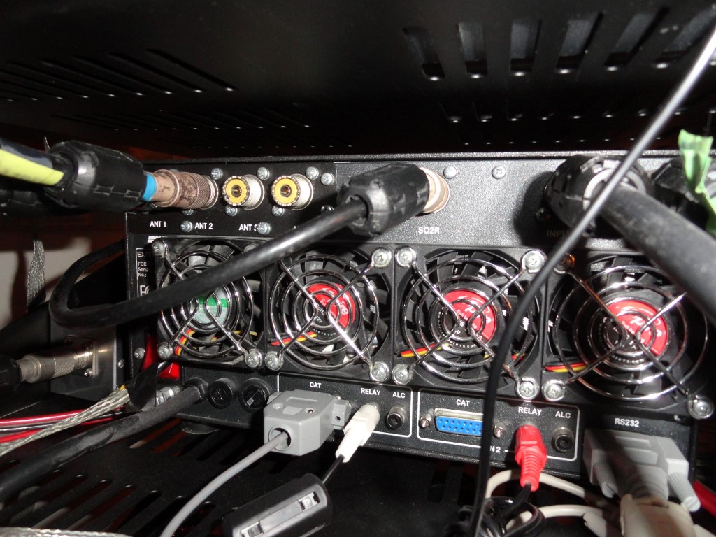
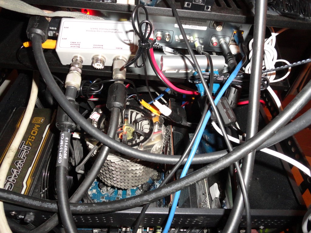
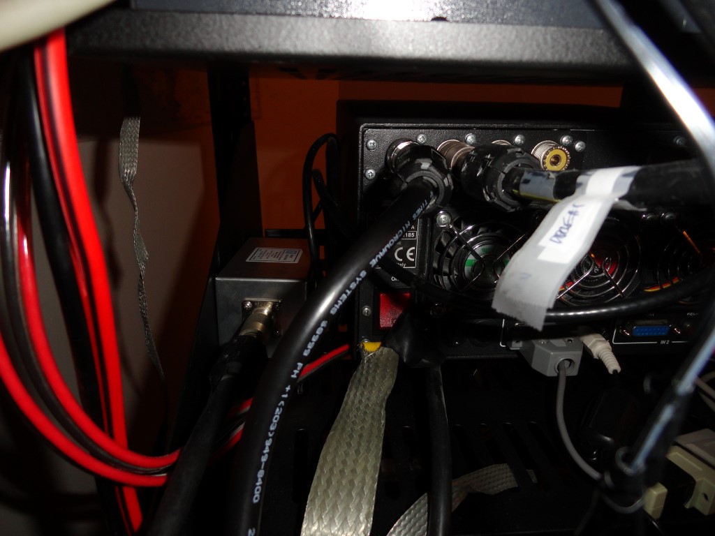
Rack Mounting Project

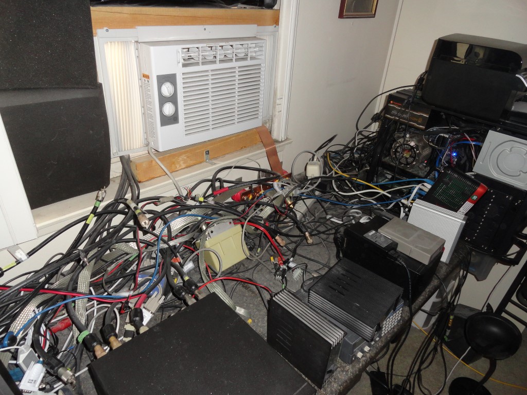
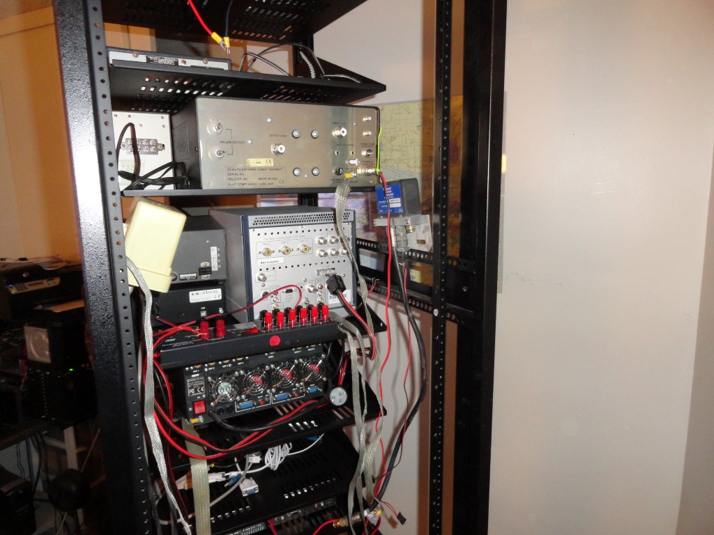
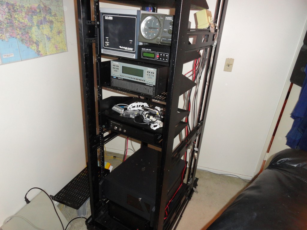
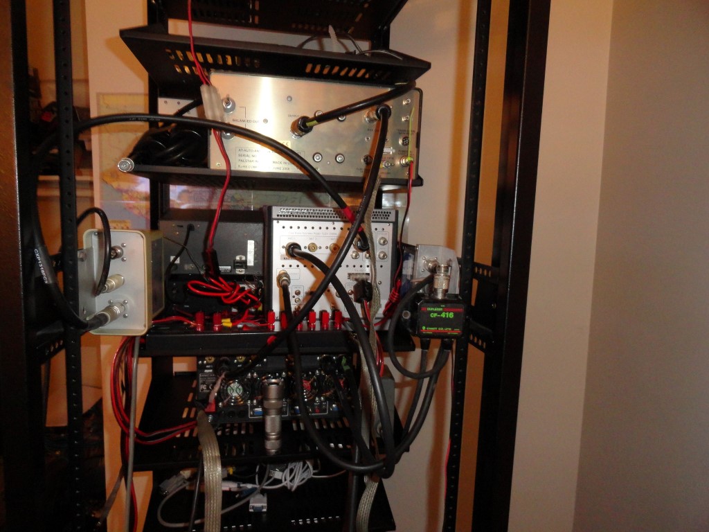
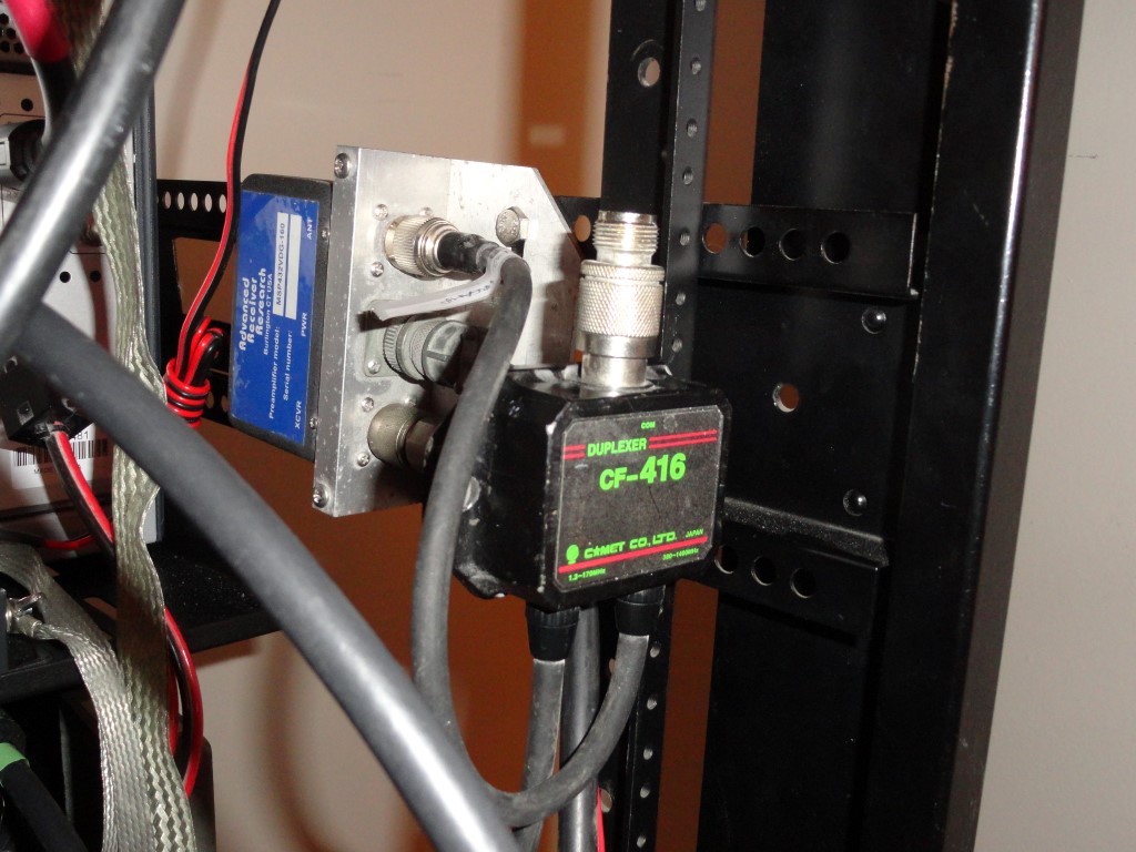
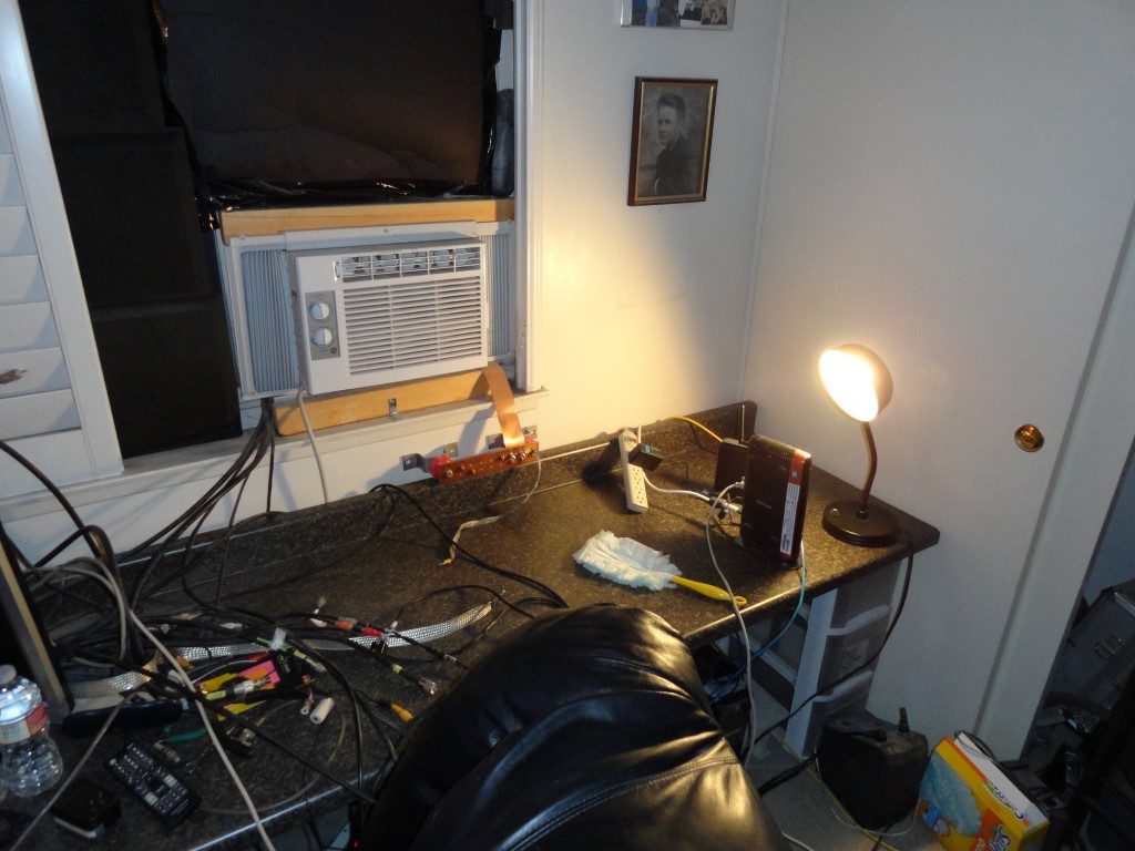
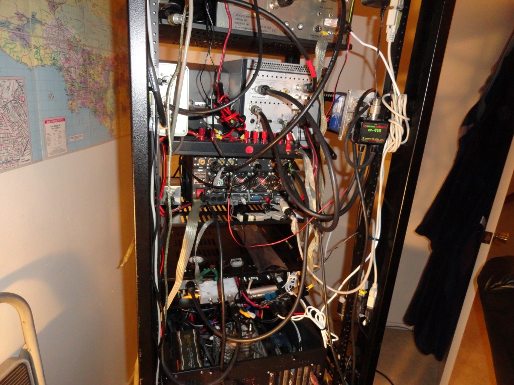
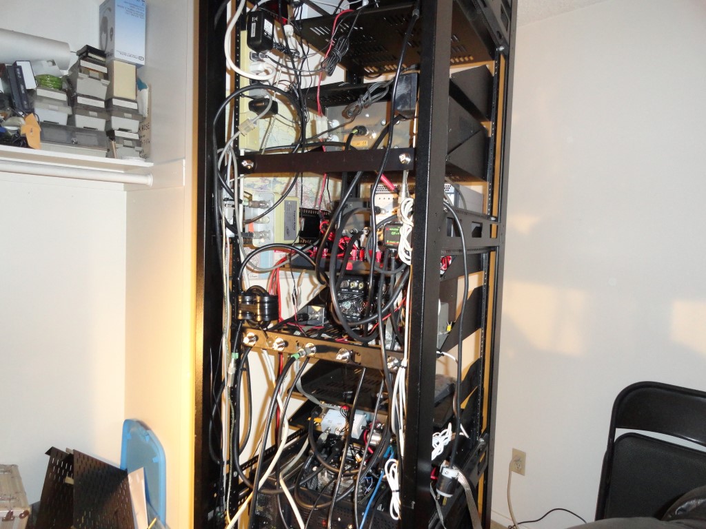
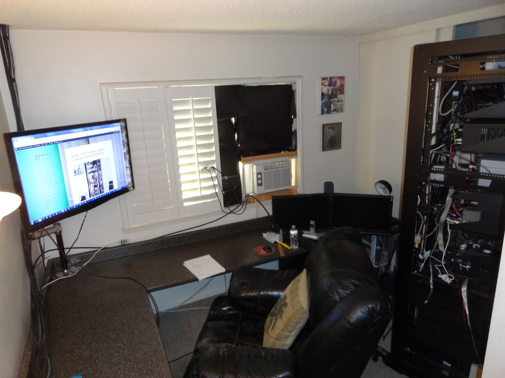
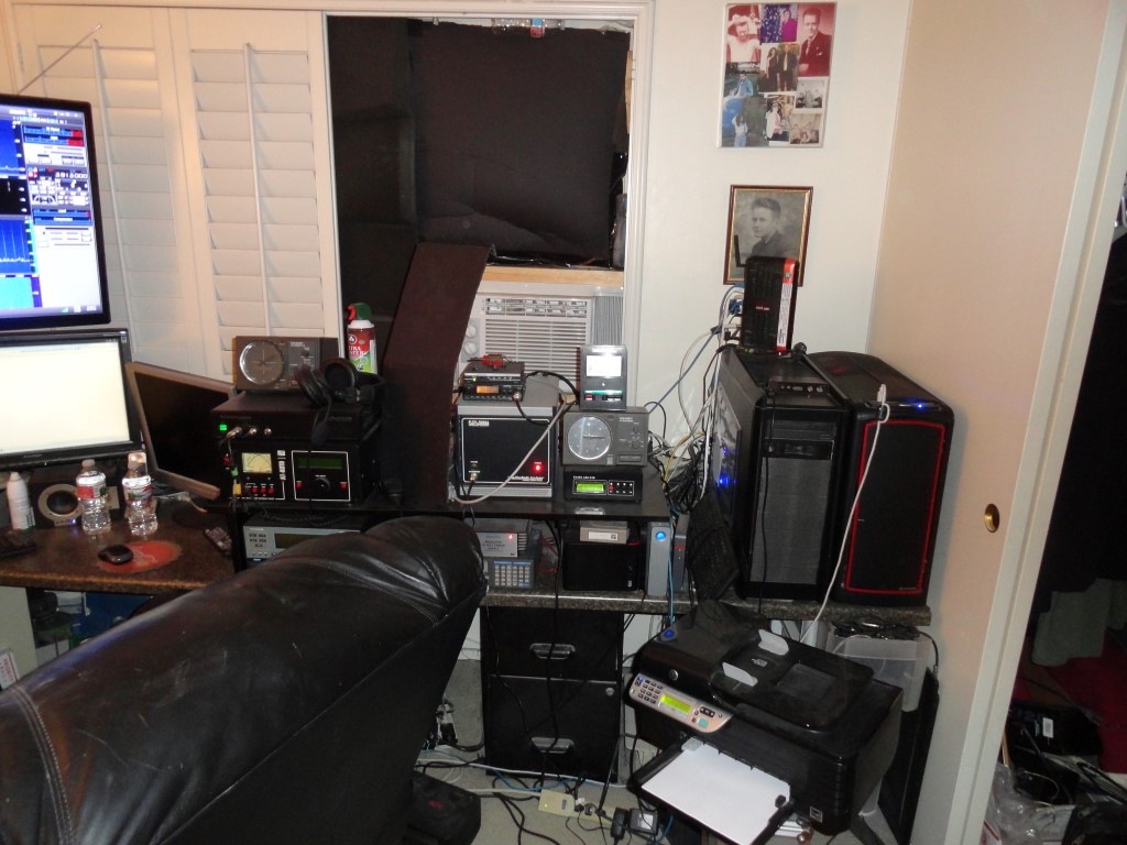
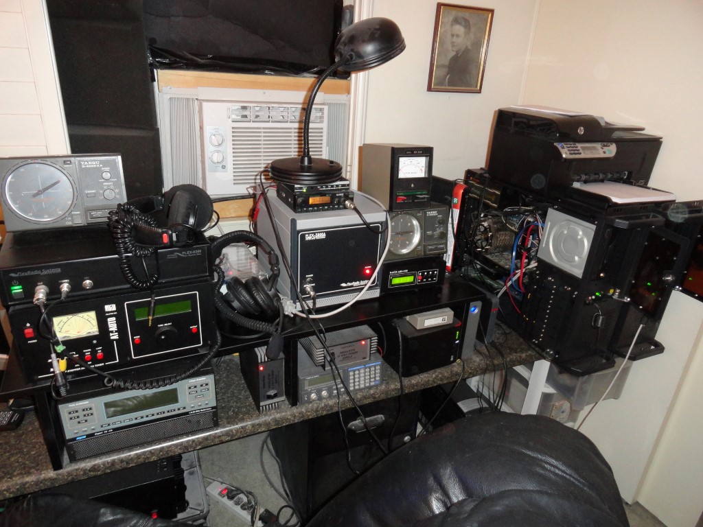
Well, as you can see, the shack is overdue for a seriously needed overhaul! Follow along as I tear this all down and rack mount it. It’s a BIG job, and it will have to be finished before March 3rd. The Rack Mounting Project is officially underway!
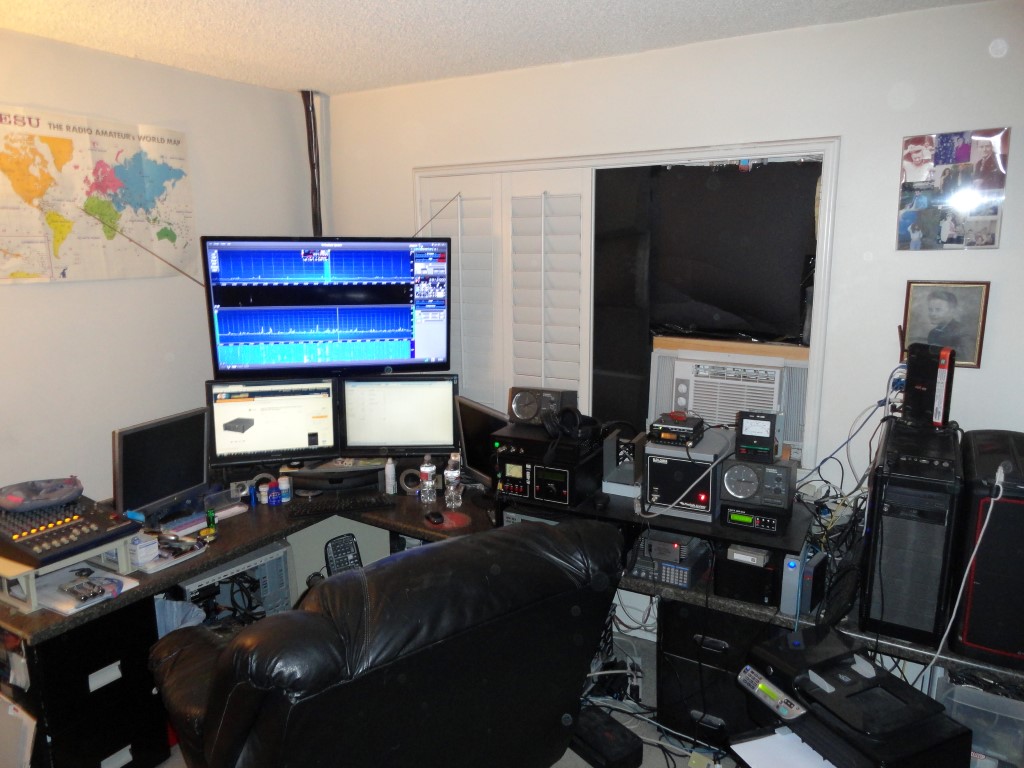
K6HR - DM03xv
This will serve as the “Before” picture for the shack overhaul blog

There’s no room for any additional equipment, and trying to work with any of the cables behind the current setup is nearly impossible! I tried adding a TV riser so I could stack more gear, but I still ran out of space.
Rack Mounting Project
I’m out of space both horizontally and vertically. Time for a change!
Rack Mounting Project
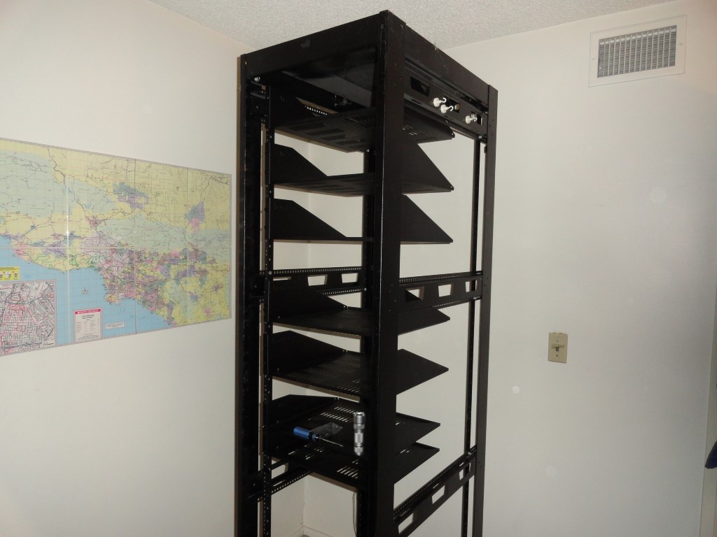
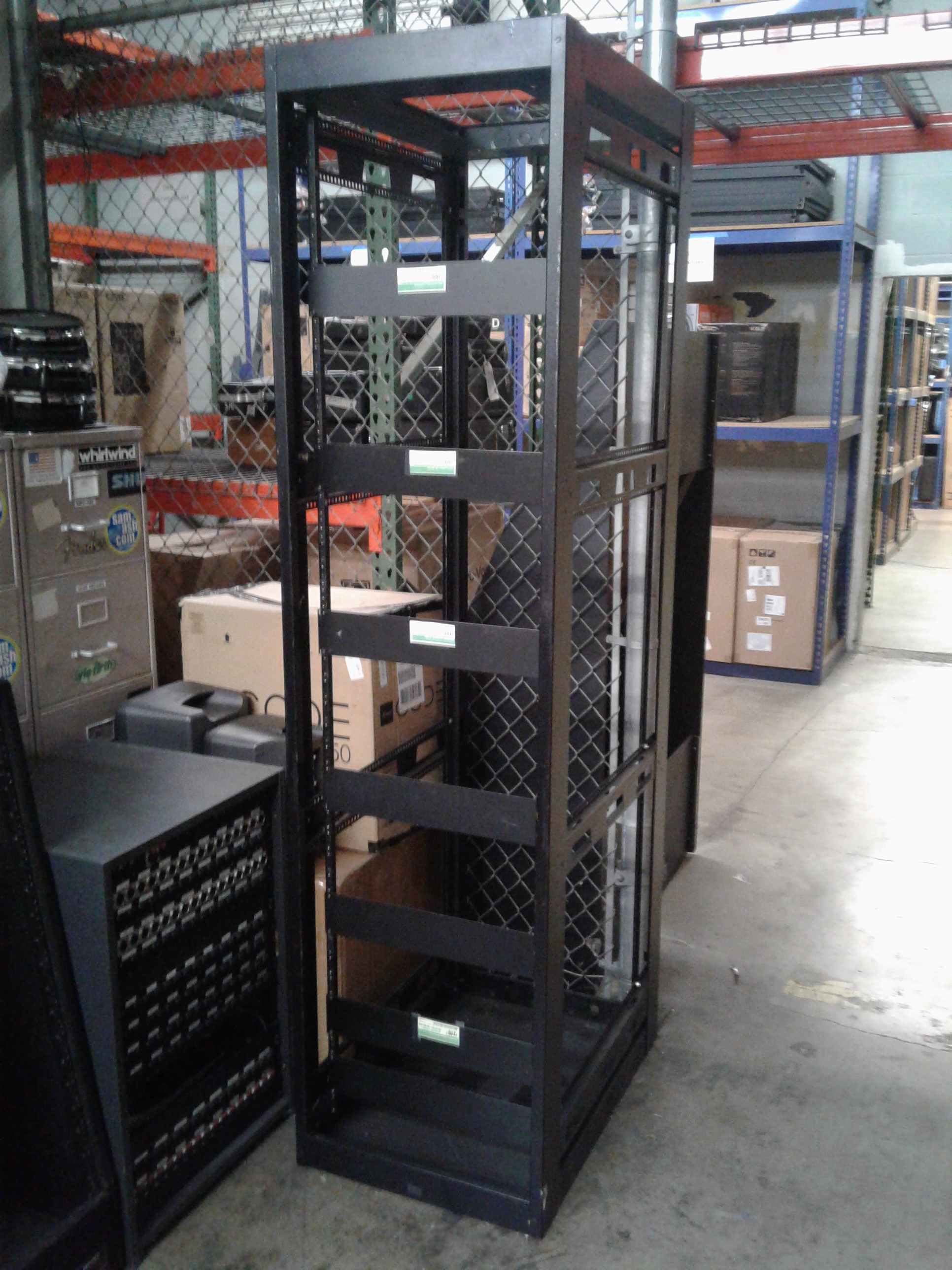
Rescued from the scrap pile, this rack would eliminate my horizontal radio sprawl!

A Nice Save!

I came across this 44U server rack as it was heading for the scrap heap, and got the idea to “go vertical” and transform my radio room into a much more productive space. The idea for the rack mounting project was born!

Yes, this would involve significant planning…<grin>

I started with a measuring tape.

  • Will this rack even fit in my room?
  • Could my gear fit in this rack?
  • How many rack spaces will I need exactly?
  • What hardware will I need in order to mount everything?
  • How will I move it around?
  • There are Grounding and DC distribution considerations
  • Vertical Layout Planning

Once I could see all these numbers were falling into place, I made arrangements to get the rack dropped off. I got the idea sometime in September or  October and started measuring. I had the rack delivered in early November, and started ordering all the parts.

Advance Planning

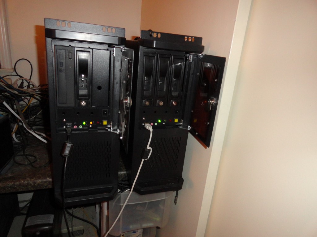
At this point I’ve resolved the mobility issue (Craftsman Mobile Base), rack mounted all 3 PC’s and removed all the unwanted furniture and clutter from the radio room so I’ll have room to start the build.
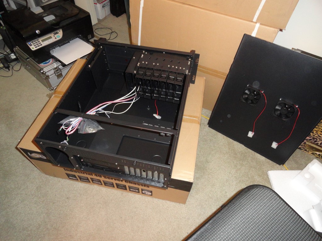
Unboxing the PC rackmount cases
L to R: Windows 7 PC, Ubuntu 13.04 Server

The PC’s went into the rackmount cases without a hitch. I’ll mount them once the shelves arrive.

Today I took a second look at WordPress and decided to install it on the web server here in the shack. It was easy to install, and appears to be up and running OK.

I plan to document the steps taken to complete this rack mounting project as I go along, while at the same time learning WordPress and planning the repair bench that will follow the rack conversion. Right now the rack is still in the garage and will likely stay there until after the holidays.

Back To The Front

Ergonomic Layout

I have just enough space to rackmount everything. Considering I also have rear rack rails, some less important items can be mounted from the rear. This is all about the ergonomic layout. I may even build some breakout panels for the antenna and audio connectors. I’ll be using a combination of 2U and 3U rack shelves (special thanks to the folks at Gator Rackworks!)  I had to go 3U for some shelves in order to get a useable depth. Most of the radio gear will sit on shelves.
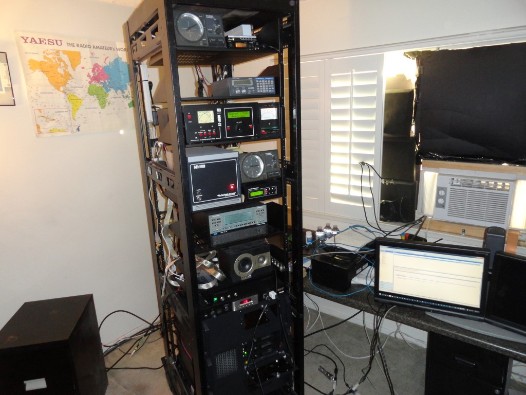
The current layout plan (from top to bottom):

  • ROTOR SHELF       4U
  • AT-AUTO HI           4U
  • AT-AUTO LO           4U
  • 2M RADIO / TNC   1U
  • FLEX VU5K            6U
  • 1K-FA                      4U
  • FLEX 6300             2U
  • FLEX 6700             2U
  • AC POWER             1U
  • PC#1 W7                4U  <<< DESKTOP
  • PC#2 W10              4U
  • PC#3 SERVER        4U
  • ASTRON RS-70      4U

I need the radios and amplifier close to the desktop, placing other ‘less touched’ items either down below or up above. I think the ergonomics are OK at this point.

Before I can start building I have to empty the shack so I can remove all the dust. I have a significant dust problem. And the problem was most apparent as I swapped out the cases on the two production PC’s. Choking on dust.

The plan is to empty the room, and mitigate the dust. I plan to use an air compressor to blow off the dust that’s embedded in the stucco-like ceiling, then, I’ll thoroughly vacuum before having the carpet steam cleaned. Going forward I will employ an oversized HEPA filter in the radio room which will run 24/7 to capture all particulates and hopefully eliminate or at least vastly improve my dust problem.

Back To The Front

Working on SEO

I just figured out how to add plugins to WordPress. I installed the  ‘Head Meta Data’ plugin that inserts information for Search Engine Optimization (SEO) into your page code. I am unable to find a single Google search result for this website. The plugin is now running with all the correct metadata.

SEO
Yoast SEO will help the web crawlers understand the content in my web pages

Update: I am unable to validate my URL through Google Services. Probably because of the .ampr.org domain name. It may finally be time to register a commercial URL.

02/19/18 – I was finally able to validate the website through BING. Later for Google, too much of a hassle.

Back To The Front

Soon To Be Rack Mounted!

Now the real fun begins as all this must be torn down. All this gear is soon to be rack mounted to eliminate the clutter.

Soon to be rack mounted
One last look at the old setup. Tomorrow 12/30/17 I begin rack mounting all the equipment.

All this gear is soon to be rack mounted. I did some major dust removal today. Now the room is empty and we will haul the rack up the stairs tomorrow. I’ll start by installing the shelves and mounting hardware etc. The following day (New Years Day) I’ll start placing the equipment and start the wiring.

Back To The Front

Installed The Shelves – Gator Rackworks

The rack is now in the shack! It was easy to slide it up the carpeted stairs. I plan to load up all the radio gear on New Years Day. Today I installed the shelves. Thanks again to Gator Rackworks!

Installed the shelves thanks to Gator Rackworks
We moved the rack from the garage to the shack and installed all the shelves today.

Making It Mobile

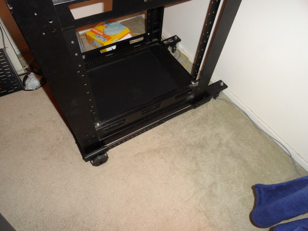
Here’s a look (below) at the Craftsman Mobile Base. You would normally use this adjustable size dolly to move your big heavy toolbox around the shop. Two of the wheels swivel (and have locking levers), the other two are fixed. I considered both the OEM wheel kit, and casters from Lowes. Then, I discovered the Mobile Base and it was less expensive than both of the other solutions.

When I installed the shelves I had to have the wheels in place
The Craftsman Mobile Base – Usually used to move heavy tool boxes around your shop or garage.

While installing the shelves I decided to make a ‘rack real estate’ change of plans. I will allocate room for a Flex 6600 (4U) as opposed to the 6700 (2U) that I originally planned for. I shifted things around and made room by taking advantage of the area above the top rack space. The rotor controllers will be on the top shelf and they will easily fit using the spare space normally occupied by a fan assembly.

Planning For Room To Grow

Nowadays I’m watching the price of used 6700’s very carefully. I think the 6700 may become legacy hardware (just like my 6300 has) once the 6600 starts shipping. The 6600 will sell for $4000, which means you could buy two of them for just a little more than the current cost of a 6700 which is $7499 at the time of this writing. Why would anybody buy a 6700 after the 6600 hardware comes out? Right?

Well, if something were to change with the 6700 and I suddenly found I could buy two used 6700’s for somewhere near the price of a new 6600….or, I could buy a used 6700 and a new 6600 for close to $7499…then I might just go in that direction. I’m hedging my bets.

Either way, now the hardware will fit in the rack whichever way I decide to go…which I guess, is the real point here…

Back To The Front

New Years Day 2018 – Rack Mount Day

Here we go! The station is disassembled and most of the equipment is in the rack. I got a lot done today. Back to work tomorrow so progress will slow during the week. I was able to rack mount almost everything.

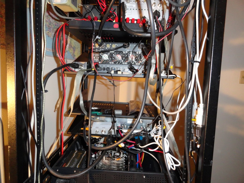
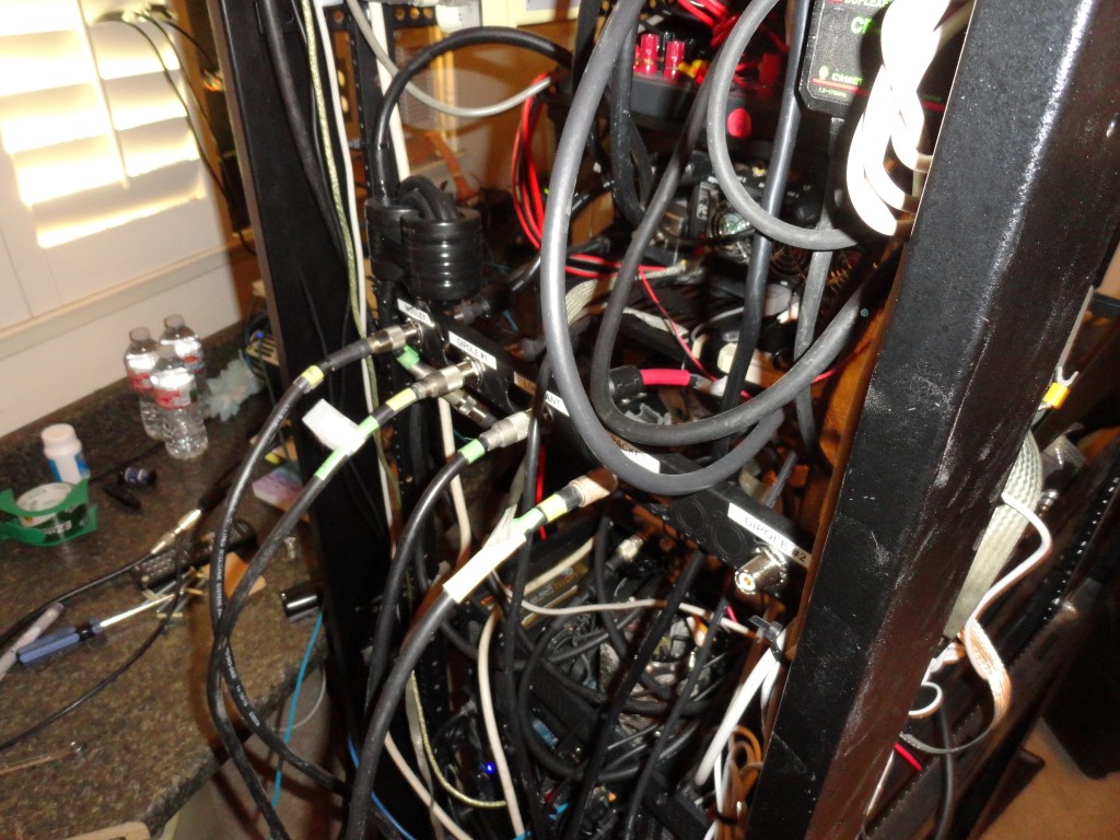
Now you can see why I needed to get moving on this. Whenever I needed to trace a cable back there it was virtually impossible. It was a rat’s nest, and, I could no longer reach behind the gear once I added the TV riser. This is what happens when you don’t have a walk space behind your desk. Even worse, every time I added gear, I would just overlay the cables in the back! Hence the rat’s nest.

Cabling rats nest
This is what it looked like behind the TV riser. Never again…

During my research for this remodel I looked at a lot of shack photos for ideas. Special thanks to Roger K7ERQ for the detailed desk plans and layout he sent me, that really got me thinking. All these great looking and functional shacks had one thing in common…They all had a walk space behind them. So I knew I had to have the ability to walk behind and work behind my gear, albeit for the first time after all these years!

The dust was unbelievable today. I was choking on the dust. Never again! The new shack will employ an oversized HEPA Filter. By the time I’m done, this room will be dust free, and stay that way thanks to the air purifier. I know, why didn’t I think of the HEPA filter sooner!

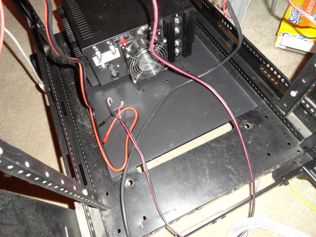
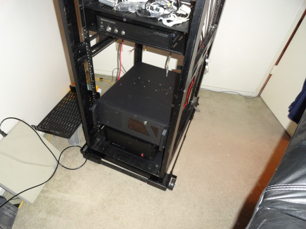
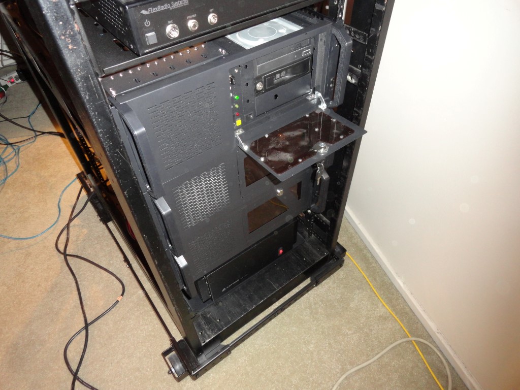
The Astron RS-70A power supply will have a PC mounted above it. The PC case is much deeper than the RS-70 which would have made it difficult to access the power supply. So, I came up with the idea to use this leftover cover from a PC to sit the power supply on.

Astron RS-70A
Makeshift sliding shelf for the Astron RS-70 Power supply

There’s enough clearance with the PC mounted above so I can slide the power supply forward or backward for service!

Astron RS-70A
The Windows 10 PC mounted above the Astron Power Supply is deep!

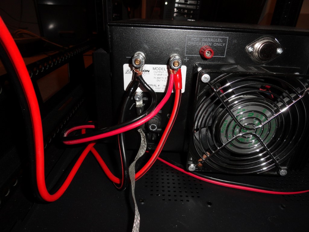
I connected the Flex 6300 directly to the power supply. I also connected an MFJ-1118 to get DC distribution to all the other components. I’m considering some of the Samlex power supplies to replace my aging RS supplies.

Astron RS-70A
Only two direct connections to the Astron RS-70A

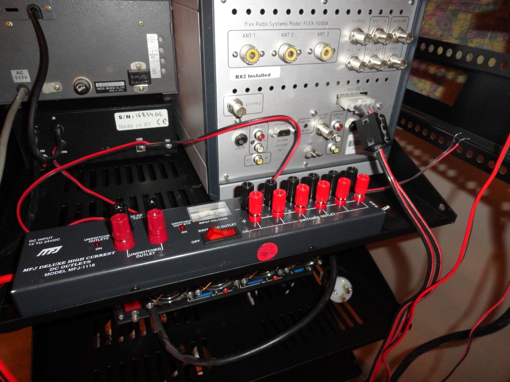
I’m connecting the Flex 5000 to the 35A terminals on the MFJ after discovering during planning that the 5000’s power lead would be too short to reach the RS-70 at the bottom of the rack. The 5000 only draws 25A max on TX, so the 35A DC distro panel was chosen. When I add the 6600/6700 radio later this year, it will also be connected directly to the power supply.

MFJ-1118
The Flex 5000 will connect to the 35A terminals on the MFJ DC Distro

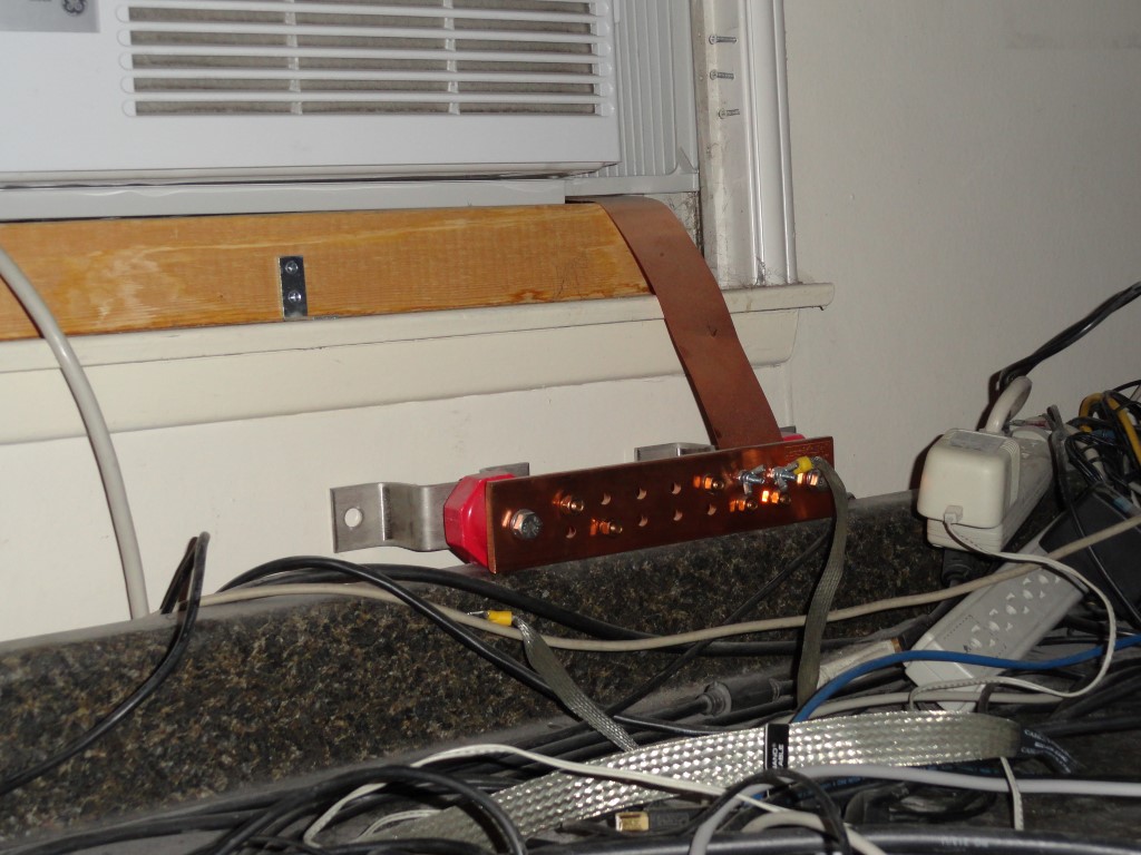
I also connected all the Single Point Ground leads. They will all tie to the station Grounding Bar which will be mounted on a rear pack panel when the project nears completion.

Georgia Copper
The Ground Bar will be mounted on a rear rack panel. The 2″ strap will be extended to meet the rack in the corner of the shack.
Single Point Ground
The Single Point Ground leads are also in place.

All the leads will be trimmed and dressed to make the wiring as clean and concise as possible. The complete opposite of what it was before. I also ordered sufficient numbers (and sizes) of Mix 31 Snap-On Ferrites. I will have proper fitting ferrite beads on both ends of every cable in the rack for RFI suppression.

Rack Mount everything
Good progress made today! The rack is getting heavy, but still rolls like a champ on the carpet!

I’ll continue wiring weeknights after dinner.

Back To The Front

Mode J Desense Filter – Steady Progress!

Steady progress today as the Mode J Desense Filter and the following items were completed:

  • Mounted the VHF / UHF Satellite Preamps
  • Mounted Mode J Desense Filter
  • Connected all the RF jumpers
  • Connected all remaining DC
Mode J Desense Filter
Installing the AMSAT Mode J Desense Filter

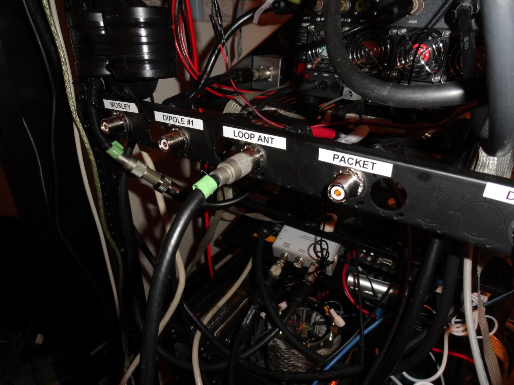
The AC power is next, then the panels for the rear RF connectors. Several antennas will connect to SO239’s mounted on a rear rack panel for quick disconnect and coax cable strain relief. The two HF antennas will connect directly to the amplifier output (Mosley), and tuner output (HF Dipole) respectively.

Mode J Desense Filter
Mode J Desense Filter as recommended by AMSAT. The 2m side of the duplexer connects to a dummy load (not shown)

The Mode J Desense Filter info from the AMSAT website.

A Simple Desense Filter for Mode-J Satellites

Background

If you have a hard time hearing your own downlink but have no trouble hearing other stations, you may be experiencing “desense.” Desense is where your transmitter signal overloads your preamp (or receiver) causing it to become temporarily less sensitive. This overload condition may also be accompanied by white noise or intermodulation distortion where you hear distorted signals in your receiver, including possibly your own transmit signal, but only when you are transmitting. If reducing your transmitter power clears up this condition, you are most likely experiencing desense. Desense problems can occur on any frequency and even commercial radio installations sometimes experience these problems, but it is especially common when transmitting on 2 meters and receiving on 70 cm to work mode-J satellites.

Several solutions exist and an easy one is to just reduce your transmit power. This may solve the problem but it will probably limit your ability to operate when satellite conditions are difficult such as near AOS or LOS or when the satellite transponder is especially busy.

Another way to solve this problem is to increase the separation of your 2 meter and 70cm antennas. This will always work if you get them far enough apart (10-20 feet) but it may not be practical for many stations.

A third solution is to install a high-pass or band-pass filter in-between the 70cm antenna and the preamp or receiver. An easy way to accomplish this is to use a 2m/70cm duplexer. Note that technically these devices are diplexers but nearly all hams and ham radio manufacturers call them “duplexers.” A typical device provides 60dB of rejection betwen the 2-meter and 70cm ports and this is generally sufficient to eliminate a desense problem.

Back To The Front

Full Day To Radio Build

Made some good progress again today on the radio build:

  • Sorted cables and cleaned the desktop
  • Mounted the two remaining PC’s
  • Ran AC supply lines and UPS
  • Setup Common Mode Choke
  • Completed some PC wiring
Radio Build
The desktop is cleaning up nicely. Future TRX workbench. See those closet doors? They are a problem…

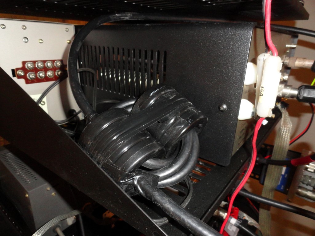
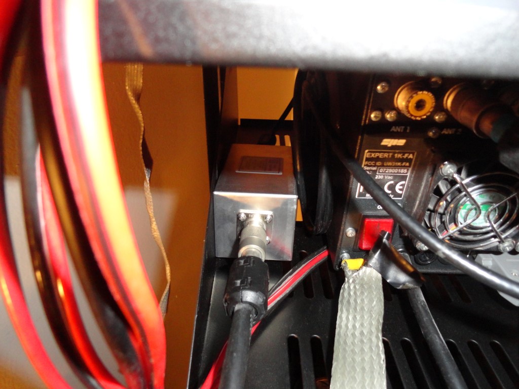
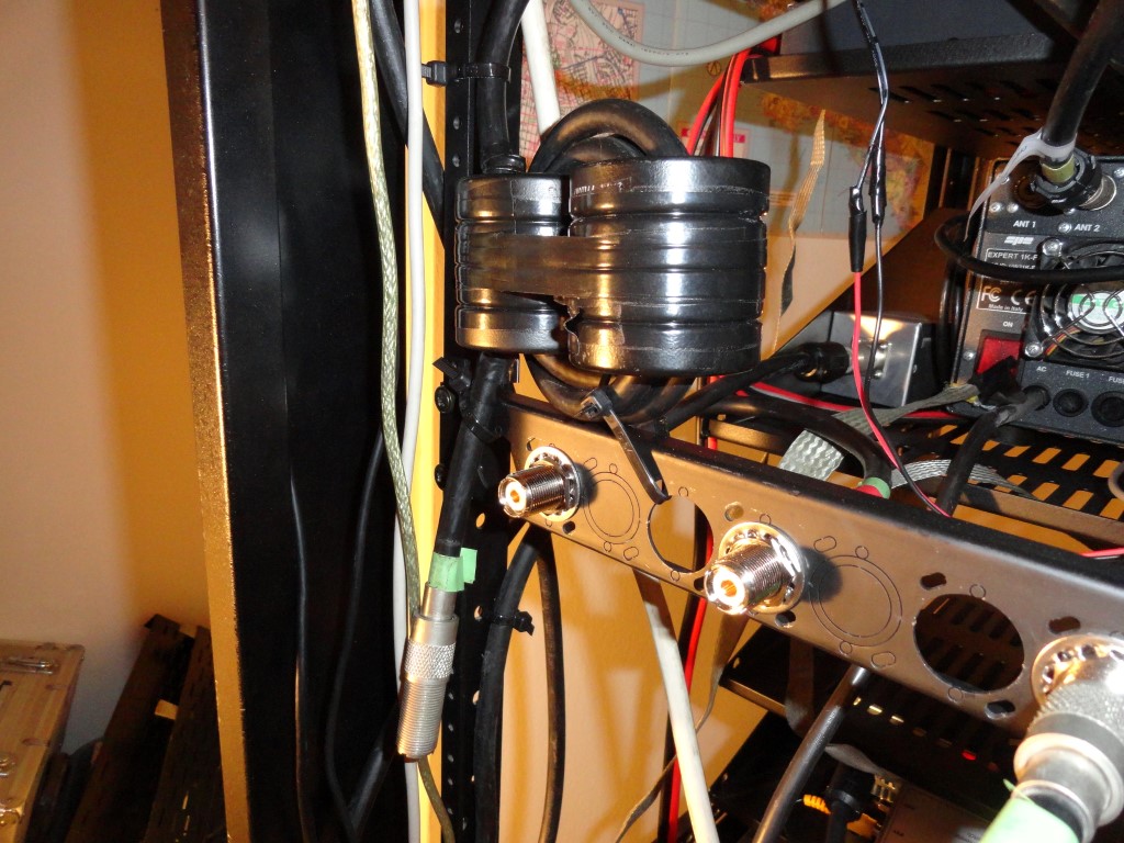
Common-Mode Choke: Research lead me to this great article by Chuck W1HIS. This design will easily handle 1KW output. The choke is inline with my 130ft (height compromised) dipole antenna that I use on the lower HF frequencies.

Big Choke For Radio Build
Common Mode Choke: W1HIS design

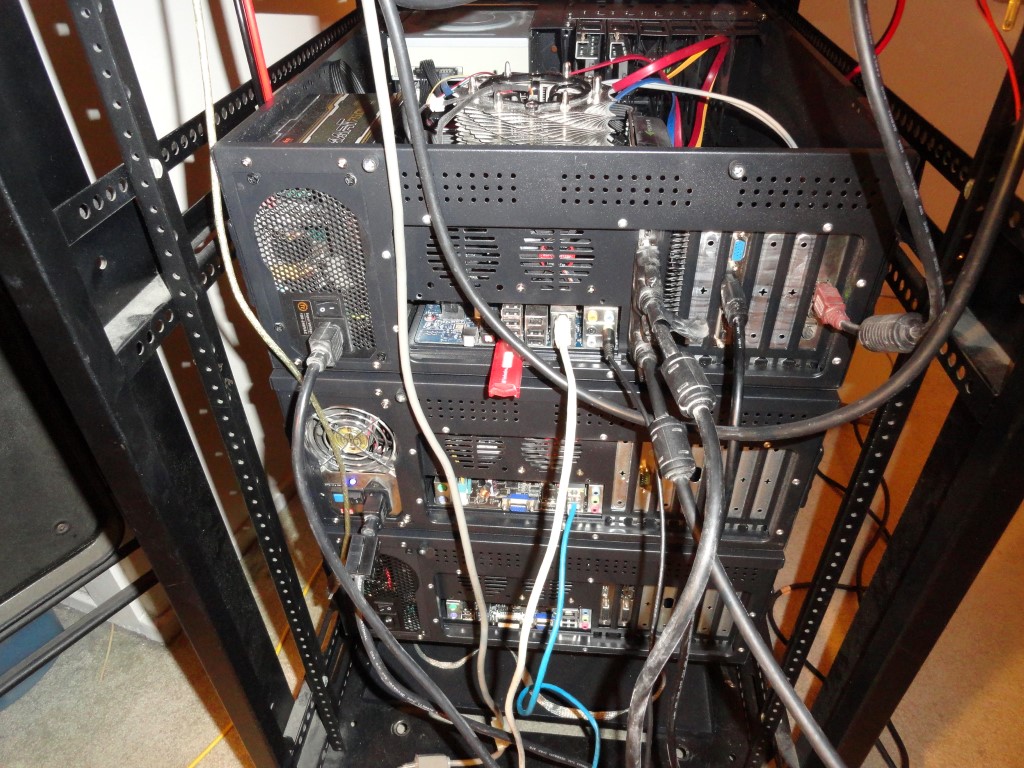
I mounted the last of the PC’s today. The server is back online after approximately 10 hours of downtime. Temporary cable connections were made to get the workstation and server back online asap.

Radio Build - K6HR
Business end of the PC’s (Top to Bottom) Windows 7 64, Ubuntu 13.04, Windows 10

One of my measurements was incorrect. Can you tell which one? You are correct! My measurement for the CPU cooler was way off. I could change the cooler or leave the top off. The PRO 2500 power strip will go in the rack space above this PC since it is only 9.5″ deep, no problem.

Radio Build - K6HR
Evidence of the dust problem! That fan is running directly off 12v (no PWM). Probably too fast, hence the extra dust. It’s quiet enough so it stayed. Soon all the dust will be gone!

Tomorrow I plan to complete all the internal wiring. Everything will be reconnected with proper fitting snap-on ferrites on both ends of every cable. The antennas will be reconnected using temporary cables until the rear antenna breakout panels are ready. In the previous setup I had several long USB extension cables, long monitor cables, and long audio cables which acted like antennas and introduced RF into the PC’s and other shack devices. I eliminated any RFI problems by choking off cables one by one anytime trouble came around. On some cables (like my Heil headset) the snap-on ferrites could be ‘unsightly’ and/or create cable strain.

Another benefit of the rack installation is the elimination of all the long cables. Replacing them with short (correct length) cables with ferrite chokes on each end will absolutely eliminate all RFI issues, and, improve RX quality.

The next phase of the remodel will be the furniture movement. Since the rack is 22″ wide and will be placed in between the 45 degree mitre joint of the two desktop pieces, calculations show the desktop pieces must each be moved a minimum of 16.5″ in order for the rack to fit. The left desktop is free to move the 16.5″. However, the right side is not. It butts up against the sliding door to a closet (see photo above).

A decision will be made to either reduce the desktop surface by cutting off 16.5″, or, remove the sliding doors on the closet to allow the 16.5″ of desktop to extend into the closet area and eliminate the need to cut the desktop. (using a hand saw)

Where the heck am I gonna put these friggin’ closet doors….

Back To The Front

Another Full Day Of Radio!

SPE Expert 1K-FA
Cabling is nearly complete

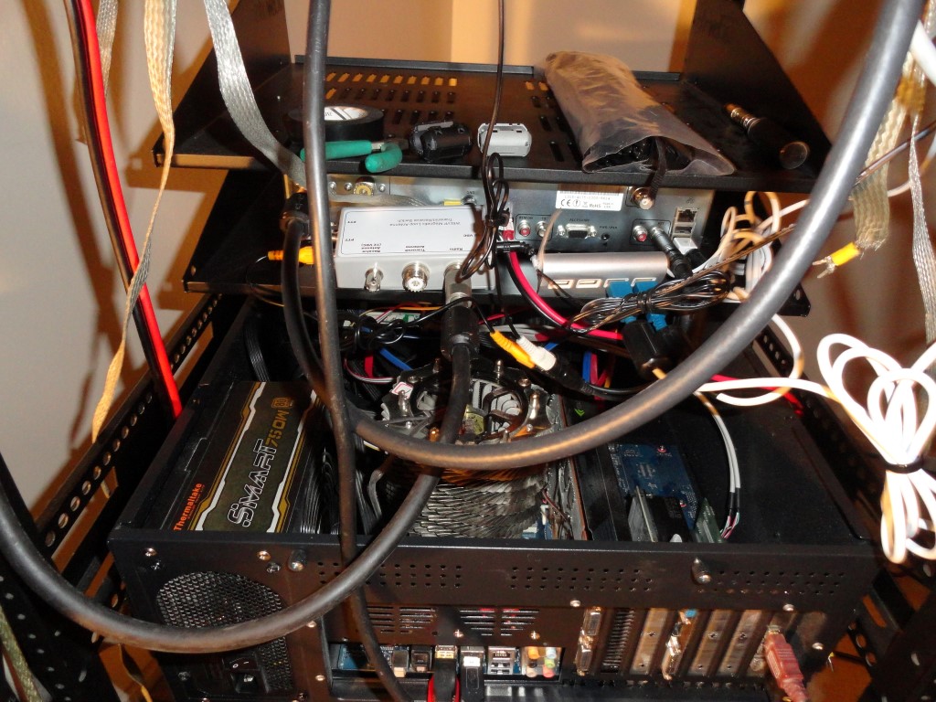
Installation of the SO2R RX Loop Antenna TX Relay

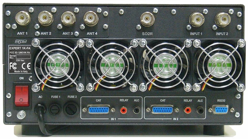
The SPE Expert 1K-FA amplifier allows connection of two transceivers, four antennas, and, an SO2R RX-ONLY antenna. When transmitting on Radio#1, Radio #2 is connected to the SO2R RX antenna. This enables the operator to listen on Radio #2, on any band, while working the latest DX on Radio #1, and vice versa. Automatically. The Expert amp does all the switching.

SPE Expert 1K-FA Linear Amplifier

SPE Expert 1K-FA
Business end of the 1K-FA. Two inputs, Four outputs, Internal Antenna Tuner, SO2R, and it’s FULLY AUTOMATIC.

SO2R operation also presents the possibility of overloading or damaging the sensitive RX front ends of the two connected transceivers. The 1K-FA manual warns of this possibility and cautions the user about antenna separation etc.

W6LVP Loop Antenna

For an SO2R antenna it is suggested (and makes the most sense) to use a wideband RX antenna on this port. In my opinion the W6LVP Loop is the best antenna on the amateur market for this purpose. Perfect for use with my amplifier. I researched them all, and chose the LVP. The loop antenna is available in a version that includes a TX/RX Relay/Power Injector box. Wait, isn’t the SO2R port on the amplifier RX-ONLY? The answer is yes, but…and it’s a big but…only when the amp is turned on. Huh? When the 1K-FA amplifier is turned off, Radio #1 is connected to antenna #1 (which in this case is a resonant TX/RX antenna), and Radio #2 is connected to the SO2R antenna.

W6LVP RX Only Loop Antenna
The W6LVP Loop TX Relay has a dedicated PTT line from Radio #2

Found A Hitch!

Under the operating condition when the amp is turned off, Radio #2 will transmit into the RX-ONLY antenna. (!No Bueno!) And by doing so, would likely destroy the RX preamp in the loop antenna. Once I realized this I ordered the TX/RX Relay and put it place with a dedicated PTT line from Radio #2 to switch it. Even though the Relay Box can auto-sense RF, I felt a PTT line would better, perhaps even faster.  Some idiot-proofing by the operator, for the operator! I was sure it would only be a matter of time before I would make this mistake, so the relay was put into place.

Array Solutions - RXFEP
Array Solutions RXFEP – Receiver Front End Protector

During my research I found the Array Solutions RXFEP – Receiver Front End Protector. The RXFEP is a low cost solution and a must have ‘failsafe’ device to protect against overloading the RX in an SO2R configuration. After all, I’ll be transmitting with over 1KW output on an antenna in close proximity to the RX Loop antenna. The Flex 6000 series transceivers have RX front end protection built-in, the Flex 5000 does not, and one can never be too careful. Insertion loss? Not enough to bother me…

SPE Expert 1K-FA
The wiring is nearly complete. I know, I have to find a shorter 9 pin serial cable!

Next I will be adding the antenna connector breakout panels, an audio breakout, and the ground bar for the Single Point Station Ground.

Back To The Front

Common Mode Choke – Friday 011218

Common Mode Choke

Common Mode Choke
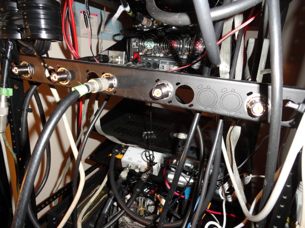
RF Breakout panel and Common Mode Choke in place

Today’s work included installation of the Common Mode Choke and the following items:

  • RF Bulkhead Connectors and Panels
  • PRO 2500 Power Strip
  • UPS Backup Power
  • Mounted Common Mode Choke

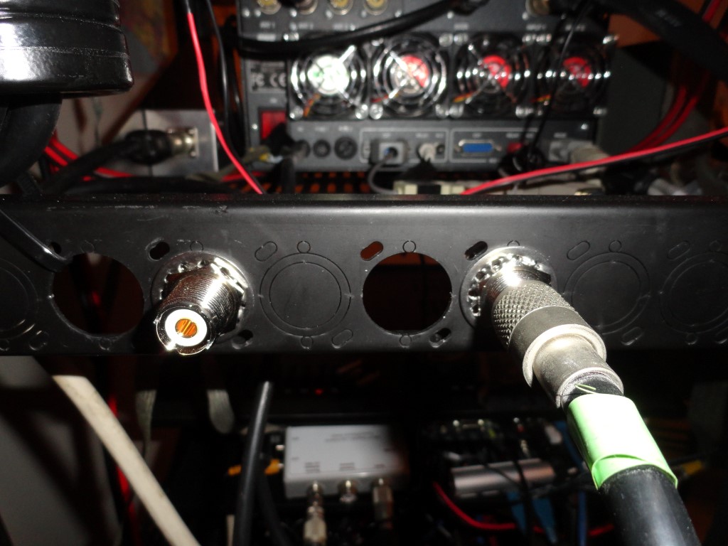
I decided to add breakout panels for the antenna connections. I want to avoid direct connections to the equipment so that when I have to move the rack I don’t have to worry about the antenna coax pulling the equipment toward the back of the rack. All but two antennas will connect via the panels. The discone antenna for the scanner, and the spare G5RV will connect directly to their receivers.

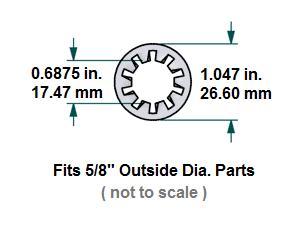
I had a few 1U panels with audio connectors on them and decided to repurpose them rather than buy new panels and have to drill them. The only problem was the knockouts were already punched out and the 15/16″ hole was too big. The SO-239 bulkhead connectors I purchased did not include any washers. I started looking through the local hardware stores and quickly realized none of them had the right size. I also saw an eHam article saying the same thing, no hardware store will have this size. I knew I had to look elsewhere. I had seen pictures of bulkhead connectors with (what I call) ring washers on them, but where can you find these washers? A pretty obscure part to try to find, especially when you don’t know exactly what its called.

During my research I was very pleased to find a perfect match at American Radio Supply. They call it a “Large Star Washer For SO-239 UHF Bulkhead Connectors”. Yep. Gotta love Google! So here I was stuck with these 15/16″ holes, and BOOM! Look at that! It’s 1.047″ wide!

Done! Ordered! Arrived today!

Common Mode Choke
Hats Off to American Radio Supply! A Perfect Fit!

I also realized the W1HIS Common Mode Choke had to be secured somehow in order to provide some strain relief. The cable that will connect here is LMR-600, since it is so rigid, I thought it best to secure the choke with the connector for the LMR-600 facing down.

W1HIS Common Mode Choke
I secured the Common Mode Choke to the rack frame using cable ties. Set the barrel facing downward for a conection to an LMR-600 antenna lead.
Common Mode Choke
I mounted FIVE SO-239 Bulkhead connectors. Perfect strain relief!

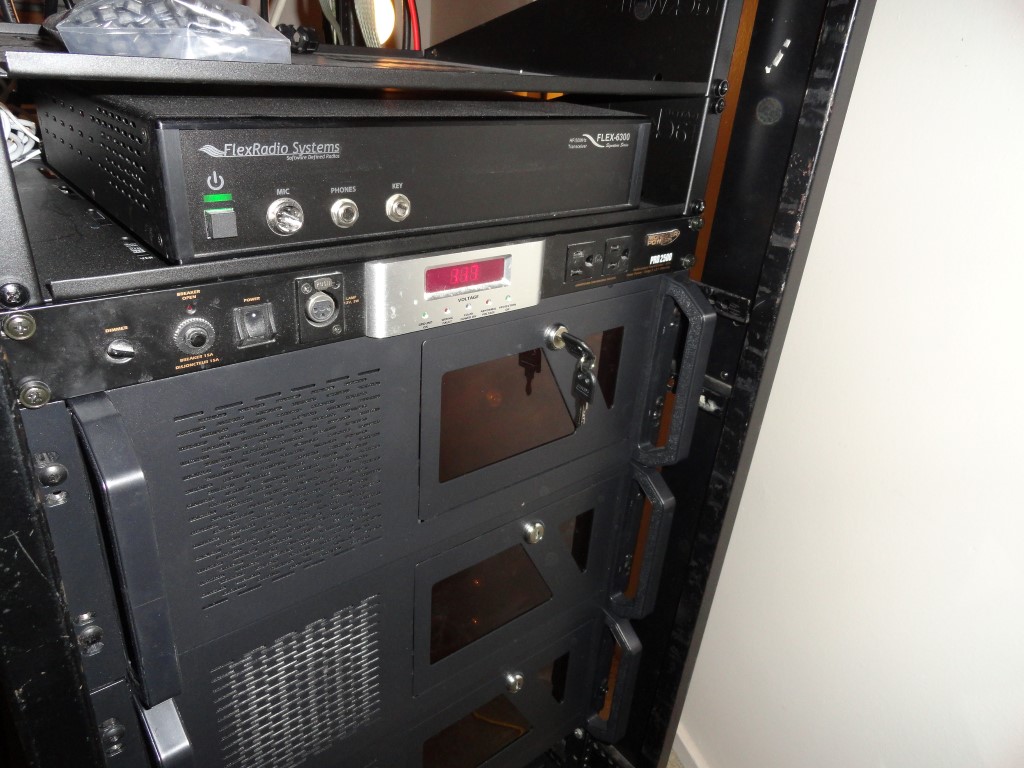
The “Monster Power PRO 2500” was installed today. I mounted it just above the desktop level, as it has two courtesy outlets on the front. The two AC power strips, and the UPS Backup are both connected to the 2500.

FlexRadio 6300
I need to reduce the fan speed on that PC!

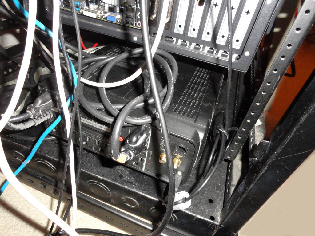
I was lucky the UPS Backup fit in the bottom of the rack behind the Astron power supply.

Common Mode Choke
The Cyber Power 1500VA UPS Backup provides approximately 30 minutes run time for the two attached PC’s.

Tomorrow I plan to remove the computer monitors and the left side of the desk so I can move the rack into a better position for testing, to where all the antenna and rotor leads will reach.

Back To The Front

Saturday Progress Report

I got started early today and got a lot accomplished. Here’s the Saturday progress report:

  • Placed parts order for 1ft jumpers (due 1/20)
  • Removed 4 monitors and cleared desktop
  • Cleared under desk area
  • Sorted all cabling, tools, and parts
Saturday progress report
Cleared the desktop!

At this point the rack is more or less electrically complete pending the installation of two more jumpers that are scheduled to arrive Tuesday. Initial testing shows everything is working as expected. Before I can move the rack into the TX test position (an area next to the desk where all the antenna coax cables can reach) I will have to split the desktop in the corner where the two pieces meet, and temporarily remove the section on the left along with the 46″ monitor and arm.

I currently have only the loop antenna connected as the antenna coax leads don’t reach the rack while it’s still in the ‘construction’ position. If all goes as planned I should be back on the air sometime next weekend.

What remains to be done:

  • Rearrange the antenna order on RF Panel #2
  • Install remaining jumpers
  • Install Secondary UPS Backup
  • Ground Bar and SPG leads
  • Satellite EL Rotor DB9 quick disconnect
  • AF output panel
  • Remove closet doors
  • Remove 46″ monitor and Ergotron Arm
  • Split desktop to accommodate rack
  • High Power testing
  • All remaining Snap-On ferrites
  • Reinstall all peripheral/office items

This wraps up the Saturday progress report

Back To The Front

RFI Battle! Choking Everything!

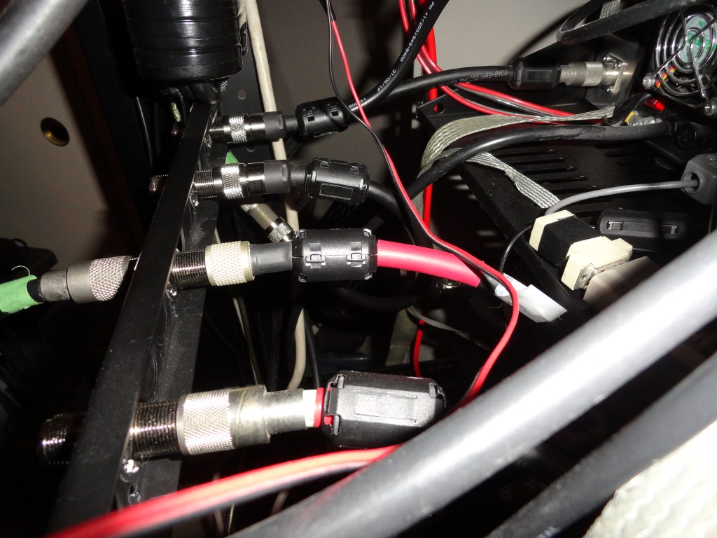
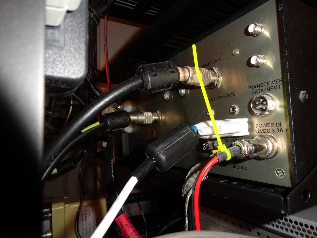
Choking everything! I’m still working through placing all the snap-on ferrite chokes. When complete, virtually every cable will have a proper fitting choke on each end. I plan to be choking everything. This really helps keep things quiet and eliminate RFI in the shack. In my previous setup I added ferrites one by one to eliminate problems, but couldn’t choke as many cables because I couldn’t reach half of them! In the rack it’s easy and I expect great results. The goal is to be RFI free at full RF output. Research showed you can never have too many ferrites. RFI suppression done right.

Labeled the antenna panel
Choking everything
All antenna leads have ferrite chokes on both ends
choking everything on at-auto
The business end of the AT-AUTO tuner
RFI suppression everywhere
The W6LVP Loop TX Switch will have a dummy load connected

The TX relay for the W6LVP Magnetic Loop Antenna will switch over to an MFJ-260C Dummy Load in the event the TX is engaged on “Radio #2” when the SPE 1K-FA is powered off. Better to be safe than sorry, even if only at tuning level output.

Both sides of the Array Solution Front End Protector are choked off also

Between the ferrite chokes and the Low Impedance Single Point Ground System the rack should perform quietly and be 100% RFI free. Of course there’s always the “Luck Of The Irish” so I won’t count my chickens just yet. High power testing this weekend!

Back To The Front

It’s Alive! Back On The Air Today! 012018

The station is back on the air today! I was finally able to get back to work in the shack today. The packet radio system is back on the air! Finally!

Back On The Air Today!
  • Removed 46″ Monitor & Ergotron Arm
  • Removed short side of desk
  • Moved rack into test position

Back on the air today. I removed a section of the desktop so I could get the rack closer to the antenna leads. Eventually the rack will go ‘square’ into the corner and the two 45 degree angle desktop sections will fit nicely against each side. It’s not visible in the photo, but the desktop still extends into that corner.

Antennas connected
All the antennas are connected

The packet radio system is back on the air, and tomorrow the SSTV Cam will return to service. Initial testing revealed a bad data cable serving band data to input #2 of the 1K-FA amplifier. Cable repaired and the 1K-FA now has full functionality again.

The HF radios are in RX only mode. There will be no TX testing before the ground system is reconnected.

Done for today!

Back To The Front

Almost Blew It! 012718

I almost blew it today! If you are familiar with WordPress you may already know what happens when you type the wrong URL info into the General Settings. That’s right, your entire WordPress website is completely unreachable. Well, I did just that late afternoon yesterday. All of a sudden all of the work I put into this WordPress project over the past 6 weeks was completely hosed, and I didn’t have a clue how to fix it.

Nerve Wracking!

Talk about nerve wracking. This is probably the worst jam I’ve gotten into.

Saturday evening I decided to register the “www.k6hr.com” domain name. It was so inexpensive at $24 I couldn’t resist. This included Dynamic DNS service. In my haste, I misconfigured the site URL’s in the WordPress SQL database. I also made some assumptions that almost wrecked the entire webserver configuration. At one point the server stopped working!

My first mistake was thinking all I had to do was change the name of my server to ‘k6hr.com’ and run the ‘homing beacon’ and I would be good to go. Big mistake. It took me hours to figure out it wouldn’t work that way. Of course, now I would have to undo everything I changed. I kept a note pad next to me and wrote down every command and edit I had performed. A changelog so to speak, so I could successfully undo it in the event of further disaster.

Database Edit Breakthrough

After several more hours of research (leading into today) and more trial and error, I found out that editing the SQL database was the only way to fix this mess. Hours of searching brought me here, and I was able to locate, backup, edit, and restore the database. Unbelievable! It looked like I could fix it. After all, to the best of my knowledge, so far I had only damaged the SQL database file, all my content etc. was completely intact. I had to learn database editing right now if I was going to be able to fix this thing.

When you don’t know exactly what you’re doing make a backup!

I created a backup file:

sudo mysqldump -p db_filename > /backup/db_filename.sql

Then I opened the backup file (as root) using the Midnight Commander file browser, (I’d be lost without “mc”) and did a search for “k6hr.com” and found the two entries I needed to change. I typed in the corrected URL info, saved the backup file, and then replaced my hosed WP database with the edited version of the backup and crossed my fingers.

sudo mysql -u <user> -p < /backup/db_filename.sql

I restarted mysqld, then attempted to load the WP admin page from my original  working ampr.org domain webserver…

It worked! What a relief!

I had successfully recovered the database after working some 14+ hours. I could now login to my WP website again! But, there was another problem, no other WP webpages would load. Only the admin page would open. I was off to a great start either way, as I had no access whatsoever a minute ago.

It turned out the first thing I changed yesterday was the last thing that needed to be reset today. It was the “homing beacon”. I noticed when trying to connect to WP pages using my original working hostname, which I just got done restoring, were timing out with an error message saying “k6hr.com” was unreachable. The URL was being redirected from gw.k6hr.ampr.org to k6hr.com and of course this could never work.

A Working Solution

I figured out that I had to uninstall the homing beacon, and delete all the DNS records it had created. On the ChangeIP.com website I found the DNS Manager and deleted everything. That was it! This WordPress website had been successfully recovered. Good thing, because I was sick over the idea of losing it to such a bonehead mistake.

Brian N1URO advised me on several aspects of getting this working:

  • Add DNS A and CNAME records pointing to my server IP address
  • Eliminate use of the Secondary HTTP port 8080
  • Add a Virtual Host to the Apache2 configuration

Updates and/or additions to DNS records can take up to 24 hours to propagate through all the nameservers on the web. So possibly by 10pm tomorrow night “www.k6hr.com” will be alive and well on the web!

Back To The Front

Two New Domains Registered

Over the weekend I registered two new domains:

I chose ChangeIP.com based on price. They are hereby HIGHLY RECOMMENDED! I experienced very fast responses to all the tickets I opened to ask questions.

Two New Domains through ChangeIP.com
ChangeIP.com

I had no experience dealing with DNS records, and I was fairly certain the DNS records were a big part of the problem I was having.

I decided to reach out to a few friends and ask for advice. Special thanks once again to longtime ham radio friend and guru of ‘All Things Internet’ Brian N1URO. Brian laid it out in simple terms, and I quickly realized I was just a few steps away from everything working perfectly.

Brian told me to:

  1. Reconfigure my Apache2 server to listen on port 80 (instead of 8080)
  2. Create 2 DNS records: An A record and a CNAME record
  3. Add a Virtual Host to the Apache2 server

All the changes Brian suggested were well documented on the web.

Years ago I used an ISP that blocked incoming packets for port 80. I was told they did this to discourage home based web servers. I discovered that they had not blocked the Secondary HTTP port at 8080, so I told my Apache2 server to listen for connection requests on port 8080. I continued to use port 8080. Since it was working, I never thought about changing it back.

Simple:

  • Edited the /etc/apache2/ports.conf file and changed the port number back to 80.
  • Logged into my account at ChangeIP.com and created the 2 DNS records
  • Copied, edited and renamed /etc/apache2/sites-available/default to /etc/apache2/sites-available/k6hr.com
  • Enabled the site with the command ‘sudo a2ensite k6hr.com’

To create the DNS entries I used ChangeIP.com’s DNS Manager. It’s a web interface that allows you to directly edit and update your DNS records. I clicked on my new domain and there was a button to “Add A Record”. Then, a drop down menu to select the “Record Type” followed by two data entry fields. After selecting A record, the first field to be entered is hostname, and the second is the IP address of your webserver. This was the same for both the A and CNAME records. Once I save the changes they take effect in just seconds.

An important step in setting up your new virtual host is creating the configuration file in the /etc/apache2/sites-available/ directory. This file contains the all important “Document Root” entry which defines the directory where all your virtual hosts’ webpages, images etc. will be stored. Typically this directory will be found in your /var/www/ directory. After running the command to activate the virtual host, an entry appears in /etc/apache2/sites-enabled/ directory and your new virtual host is ready to accept connections. The two new domains have been enabled in Apache and ready to test.

Everything is working brilliantly! Now if i could just figure out how to successfully “verify my property” in the Google Search Console I think I’ll be in business. I currently have little to no search results anywhere.

Tomorrow I plan to cut the desktop. Unless something unexpected comes up, the furniture portion of the remodel should be complete. I’m sick with a terrible cold, But I need to get the furniture squared away.

Click here to go back to the future