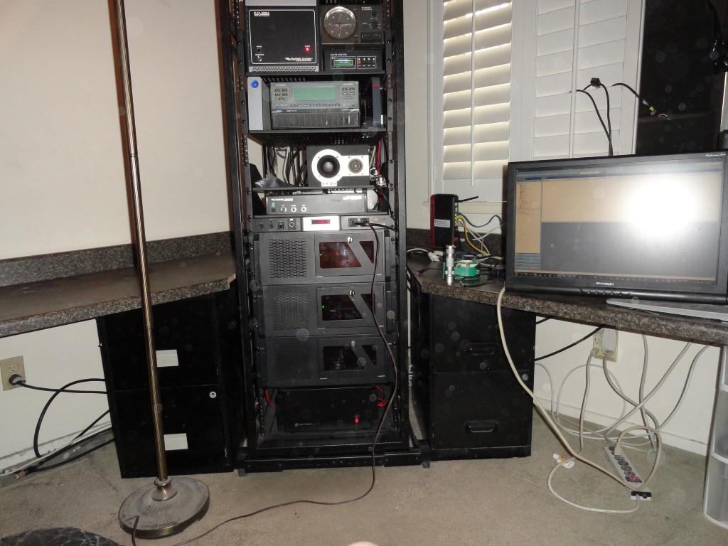
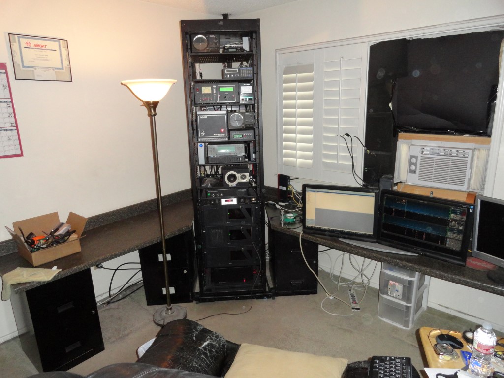
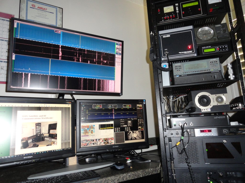
Well, as you can see, the shack is overdue for a seriously needed overhaul! Follow along as I tear this all down and rack mount it. It’s a BIG job, and will have to be finished before March 3rd.
There’s no room for any additional equipment, and trying to work with any of the cables behind the current setup is nearly impossible! I tried adding a TV riser so I could stack more gear, but I still ran out of space.
I came across this 44U server rack as it was heading for the scrap heap, and got the idea to “go vertical” and transform my radio room into a much more productive space.
Yes, this would involve significant planning…<grin>
I started with a measuring tape.
Will this rack even fit in my room?
Could my gear fit in this rack?
How many rack spaces will I need exactly?
What hardware will I need in order to mount everything?
How will I move it around?
There are Grounding and DC distribution considerations
Vertical Layout Planning
Once I could see all these numbers were falling into place, I made arrangements to get the rack dropped off. I got the idea sometime in September or October and started measuring. I had the rack delivered in early November, and started ordering all the parts.
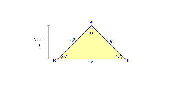
Today I made the final cut to the desktop so the rack will now fit. As seen in earlier photos of this project, the two sides of the desktop met in the corner at a 45 degree angle miter joint. As it turned out, another ham with an Isosceles Triangle Calculator came to my rescue.
One Chance To Get It Right
To fit the radio rack into the corner of the room, I needed to figure out how much to cut off of the right side of the desktop in order to fit a 22″ wide rack in between the two 45 degree angled sides. The desktop currently occupies the entire length of the wall, and shortening its length is now the only solution.
I’m no math whiz, and my guess was I would have to cut off 11″ if I were to fit a 22″ wide rack in between the two sides. Wrong! Luckily, I asked around first. The answer was found using an Isosceles Triangle calculator.
The Isosceles Triangle Calculator
All I knew was the corner was 90 degrees and the hypotenuse was 22″. Thanks to Cory AE6GW for doing the math. The resulting calculation showed I needed to reduce the length of the desktop by 15.556″ in order to obtain an exact fit. Then, I added an inch, so my sliding closet door would still have clearance.
Output of the Isosceles Triangle Calculator
Solving an isosceles triangle. The base, leg or altitude of an isosceles triangle can be found if you know the other two. A perpendicular bisector of the base forms an altitude of the triangle. This forms two congruent right triangles that can be solved using Pythagoras’ Theorem. (It’s all Greek to me)
The rack now fits squarely into the corner.
The right side of the desktop is now approx 16.5″ shorter, and of course the rack now fits squarely into the corner of the room. Exactly the way I wanted it. I say approximately due to the accuracy of the “Armstrong Saw” I used to make the cut!
Although still far from being finished, at least now I can push the rack back into the corner and make a little more room to move around in here.
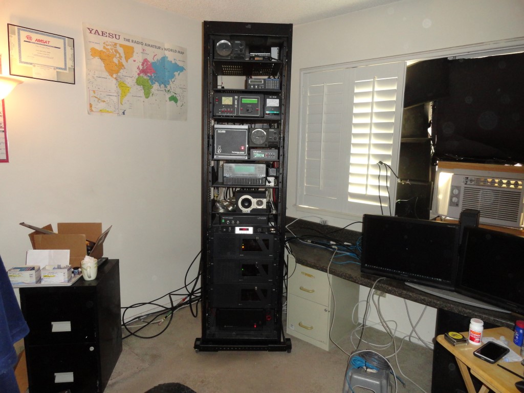
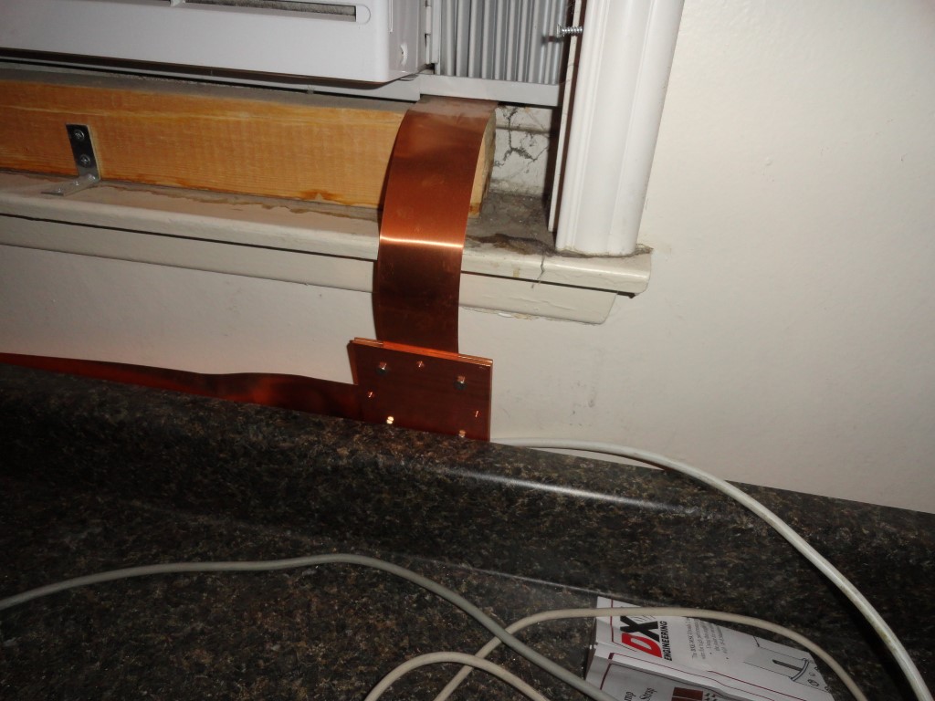
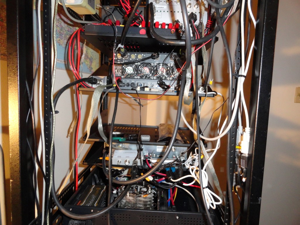
This weekend I will finish the ground bar ‘relocation’. The ground bar is currently located at the shack window . Amateur Radio Station Grounding and RFI mitigation is of the utmost importance. My goal is to provide a low impedance earth ground to the rack. Here is another series of articles on station grounding that’s really worth reading. Read these two links! Highly recommended!
This 2″ Copper Strap will extend along the wall to the rack.
Ground Bar Relocation
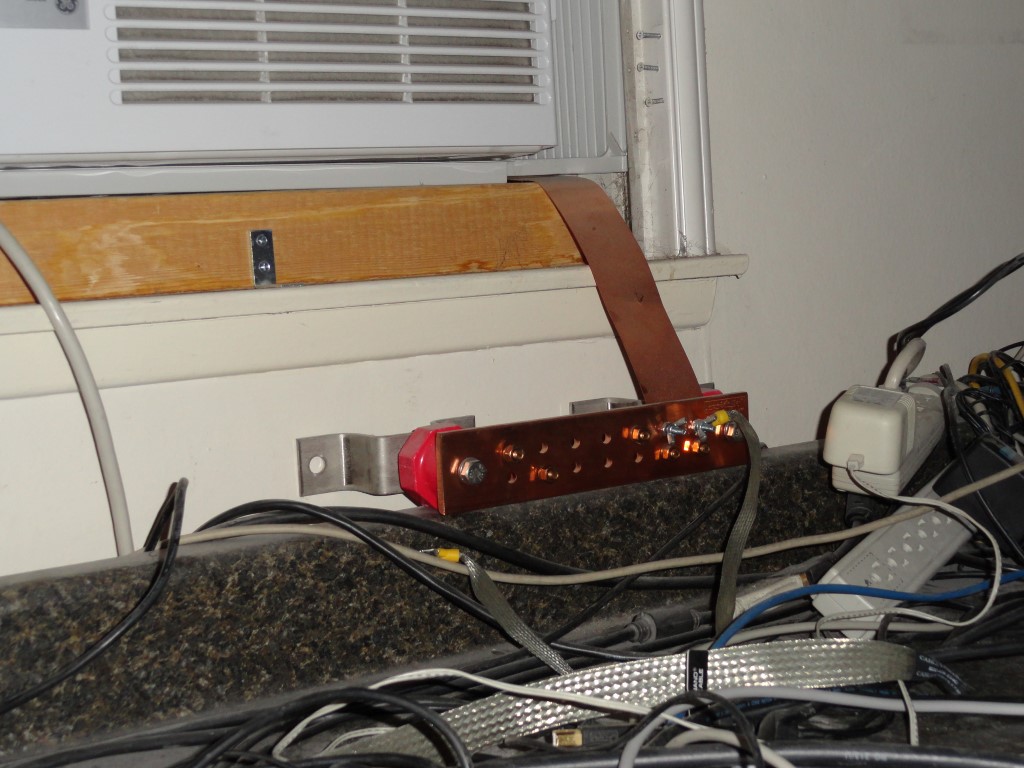
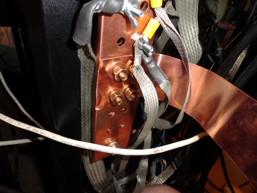
I plan to mount the ground bar vertically on the rear of the rack by bolting it to a couple of rack panels. The panels will serve as the foundation for mounting the ground bar at the correct height and position to connect the 2″ strap that’s running along the wall to the rack. All equipment will connect to the ground bar, then the strap will be bolted to the bars with some strain relief (service loop)
Ground Bar mounted!
To accomplish this I purchased a set of DXE-MSC-3 Copper Strap Bonding Clamps. The clamps will allow me to make a 90 degree turn to the left under the window, and run another piece of 2″ strap along the wall (behind the countertop). I’ll leave a “service loop” of strap in the back of the rack long enough, that I can pull the rack out for service without having to disconnect the strap. W5BWC’s article should be required reading for all amateurs who own and operate an HF station. Amateur Radio Station Grounding is just as important as the antenna!
2 inch Copper Strap left turn!
Securing The Ground Strap
Securing the loop was easier than expected. I had concerns about the loop and attaching it to the bar. Problem solved…
That’s a solid ground connection!
I traced through the holes in the bar with a paper and pencil, and created a drilling template for the end of the strap. Four 3/8″ holes perfectly lined up. Ground Bar done! At some point I’ll attach the strap along the back of the countertop so it’s not just hanging loose back there.
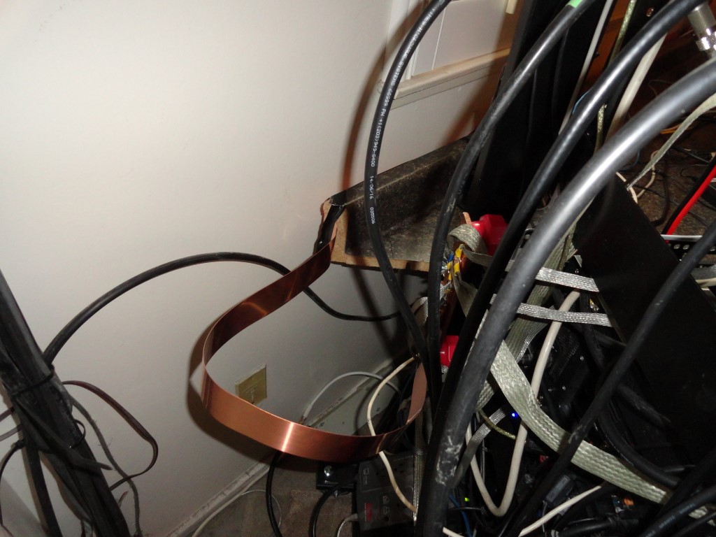
2″ copper strap loop so I can pull the rack forward for service.
Finally A Solid Ground!
The plan worked out great! I was able to push the rack all the way back into the corner, and there’s enough ‘slack’, that when needed, I can pull the rack out far enough to sit/stand behind it. This is exactly how this was planned, and I’m pretty happy with it right now.
With the desktops temporarily back in place.
I can start measuring for the finishing touches, including the addition of a 32″ 4K UHD monitor. I’m currently considering the Samsung U32H850. If it fits, this is most likely the monitor I will use to replace the 1080p TV in my previous shack setup.
The shack is finally starting to shape up! Yeah, I know, I’ll switch the file cabinet on the left so the handle colors match on either side of the rack!
Now that everything is grounded, I’ve started testing with RF. I found a couple of wiring errors to the amplifier that are now corrected. Key down at half power (600w) showed no evidence of any RF in the shack. I’ll try some full output tests tomorrow. Yeah! I finally took down that ratty looking YAESU Wall Map!
Remaining To-Do List
The ‘still to do’ list:
Relocate AC power distro
Relocate Router and Printer
Measure for use of TV riser
Measure for relocation of Ergotron Arm
Measure for 4K UHD monitor
Reconnect Scanner Audio
Reconnect Satellite Rotors
Reconnect NAS
After full power testing is complete, I will not do any more work on, or make any changes to the radio rack until after the ARRL International DX Contest (SSB) the first weekend of March. Radio work will resume after the contest. In the meantime I will get the ergonomic work going. The right side of the desktop can be completed. The left side must be done last, since access to the rack depends on sliding the left desktop out of the way.
It was money well spent on all the snap-on ferrites and on the extension of the 2″ copper strap. Initial testing shows everything is quiet and no RFI. I have a solid, low impedance, single point ground system in place. High power testing should prove the effectiveness of my Amateur Radio Station Grounding!
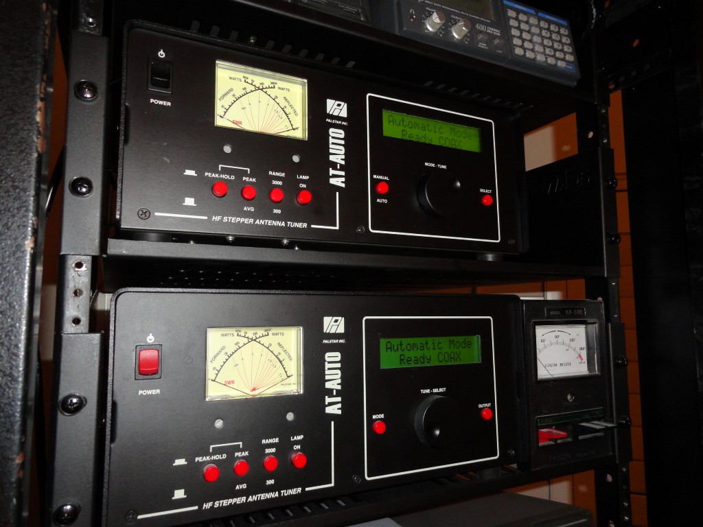
The decision was made to purchase the LG 32UD59-B 4K UHD monitor. It is scheduled for delivery on Friday (of course). This replaces the 46″ 1080p TV I was using previously. I will mount the new 4K monitor on the Ergotron Arm and position it above the dual 22″ displays, as before. I need to modify the dual monitor stand since the string/cable inside has snapped and it no longer supports any weight. I think I’ll just insert a block of wood or something to hold it up to the correct height and call it done. I also scored on a Palstar AT-AUTO.
The other item I purchased today was a much sought after (second) Palstar AT-AUTO. I found one listed online and was lucky to get it after TWO previous ‘buyers’ backed out! The unit was serviced at Kessler and had upgrades installed, so I deemed it fair to pay a little more for this one than the first one I bought. No big deal. Now I have the two I need.
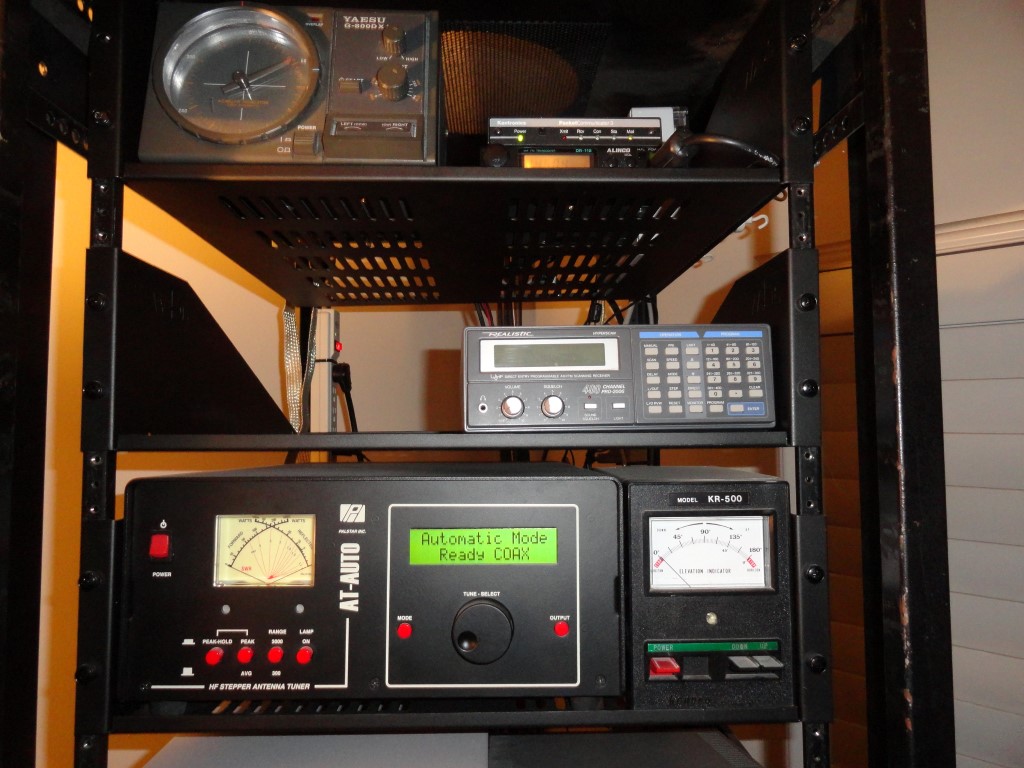
The second AT-AUTO will go on the shelf above the first one.
I’ll move that PRO 2006 scanner to the top shelf, under the Alinco data radio as originally planned, and install the AT-AUTO the same day it arrives. Tracking info to be made available tomorrow. Thanks to Robert KP4Y for what should be a very nice AT-AUTO. And…it has the same color buttons as my first unit.
The AT-AUTO is a fully automatic high power roller inductor tuner. No cranks to turn on this tuner! The AT-AUTO follows frequency changes in real-time when connected to the Flex 6000 series USB port. I consider the AT-AUTO to be one of the best auto tuners ever made. I just change to any frequency/band I please and the AT-AUTO typically delivers a 1.04:1 SWR. I no longer have to be concerned about SWR. The display is easy to read, and the tuner is quiet. The AT-AUTO does take some time to reach the tuned frequency when I switch to 160 meters, since the L and C settings for 160m are at the opposite end of the roller inductor. Other than that, the AT-AUTO typically tunes in a second or two once “trained”.
The tuner must be trained across all amateur bands so it can memorize the LC settings for your antenna. Since this unit was pre-owned, I will clear all memory before I retrain the tuner. To “train” the tuner, I transmit a tuning signal of 10w or so, and slowly tune from band edge to band edge on each of the amateur bands. The AT-AUTO stores all the LC settings in memory as you crawl each band. The AT-AUTO only has to tune, (or be trained) once. As long as you don’t change the antenna, the AT-AUTO recalls the stored settings for your current operating frequency, making tuning very fast. No worries about noisy relays, or arcing, due to its impeccable heavy duty design and construction
The AT-AUTO is a heavy duty, high power HF autotuner.
AT-AUTO – High Power, Heavy Duty, Fully Automatic, Computer Controlled, Delivering Near Perfect SWR.
From the Kessler Engineering website:
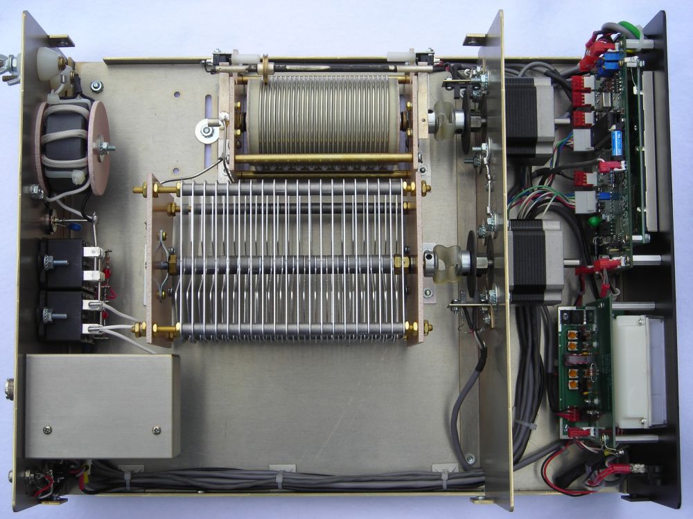
The AT-AUTO is a fully autonomous, fully automatic impedance matching network (an antenna tuner) that employs an embedded microprocessor to position a conventional roller inductor and a split-stator variable capacitor. It provides continuous coverage tuning from 1.8 – 54 MHz (including MARS, DoD, and commercial frequency bands, etc.) and is rated for 1500 W continuous carrier operation. The AT-AUTO is quiet and reliable, and with its industrial-rated stepper motors, provides a superior impedance match to that provided by the loud clanking boxes of relays provided by the competitors.
The Palstar AT-AUTO continuously measures forward and reflected RF power. As long as the SWR is below a user-selectable threshold, the AT-AUTO provides a “Good Match” cue in the Liquid Crystal Display (LCD) and takes no further action. Whenever the SWR exceeds the “Tune-Start” SWR, the AT-AUTO then counts the RF carrier frequency, looks up previously stored Inductor (L) and Capacitor (C) settings for the frequency of operation and then repositions L & C to the recalled settings. If the SWR is still excessive, the AT-AUTO automatically begins tuning, and provides user prompts during the entire process via the LCD. Once a good match is found, the new match settings are stored in memory for subsequent recall. The default behavior is highly customizable to suit individual needs.
The Palstar AT-AUTO is also able to obtain frequency information via the radio’s serial data port (for these compatible radios so equipped). By doing so, the AT-AUTO instantly follows frequency changes (VFO adjustment, etc.) and immediately recalls and sets the L & C for the new frequency – without the need to generate an RF carrier! The recalled match should provide an excellent SWR so that when RF is finally applied, subsequent tuning will not be necessary. While the serial port is not necessary for automatic tuning, this “Smart Mode” of operation greatly speeds the entire process of changing frequencies.
Note: The AT-AUTO is currently not in production and not available for sale. It is undergoing a redesign for release soon. The pictures and descriptions shown here are of the existing version(s) of the AT-AUTO tuner prior to its production cessation.
The Palstar AT-AUTO sends and receives serial data to/from the associated radio via the radio’s serial port. This is commonly referred to as Computer Aided Tuning or CAT. In order for the radio and the AT-AUTO to be able to communicate serially, an appropriate CAT cable must be used.
Because there is no defacto standard for CAT, there are variations in connectors and pin assignments from manufacturer to manufacturer. Therefore, there are unique AT-AUTO CAT cables for Elecraft, Kenwood, TenTec, Yaesu, and others. The CAT cables themselves are nearly identical, with minor variations in the specific connector and pin assignments.
ICOM has their own CAT implementation known as CI-V which uses entirely different protocols. ICOM radios, therefore, do not use the CAT cable, but instead use a CI-V cable.
Cable Sets consist of a Firmware Update Cable, A CAT/CI-V Cable, and in the case of some Kenwood radios, a Tuner-Handshake Cable. Schematic diagrams of the various cables are provided in the AT-AUTO user manual.
Finally it’s beginning to feel like the station is nearing completion. The LG 32UD59-B 4K UHD monitor has arrived, and it looks amazing. Almost everything is connected and working.
The LG 32UD59-B monitor looks great!
The AT-AUTO is the last piece of equipment remaining to be connected, and is scheduled to arrive on Tuesday 2/20/18. Today I ordered the remaining cables needed to install the tuner (two coax jumpers and an FTDI USB Serial cable)
Testing today at 1KW output did not produce any noticeable RFI in the shack! More testing will be required once all the PC monitors are in place and connected. The linear amplifier now delivers full output with 5 watts less drive It may be possible to lower the drive power even further after more testing is completed.
The rack is in the operating position and the desktop sides have been restored. The 4K monitor has been mounted and the remodel could be finished tomorrow if all goes well..
SPECIFICATIONS
32UD59/32MU59/32UD60
LCD Screen Type: TFT (Thin Film Transistor)
LCD (Liquid Crystal Display) Screen
Pixel Pitch: 0.181 mm x 0.181 mm
Maximum Resolution: 3840 x 2160 @ 60 Hz
Recommended Resolution: 3840 x 2160 @ 60 Hz
Video Signal Horizontal Frequency: 30 kHz to 135 kHz
Vertical Frequency: 56Hz to 61 Hz
Input Connectors: HDMI IN1, HDMI IN2, DP(DisplayPort) IN, H/P(Headphone) OUT
Power input
19 V 3.3 A
Power consumption (Typ.)
On mode: 39 W Typ. (ENERGY STAR® standard)*
50 W Typ. (Outgoing condition)**
Sleep Mode ≤ 0.5 W
Off Mode ≤ 0.3 W
AC/DC adaptor
Type DA-65G 19, Asian Power Devices Inc. production
Or type LCAP39, LIEN CHANG ELECTRONIC ENTERPRISE production
Output: 19 V 3.42 A
Environmental Conditions
Operating Condition
Temperature: (32 °F to 104 °F); Humidity: < 80%
Storing Condition
Temperature: (-4 °F to 140 °F); Humidity: < 85%
Dimension
Monitor Size (Width x Height x Depth)
With Stand
28.67 inches x 18.04 inches x 9.32 inches
Without Stand
28.67 inches x 16.72 inches x 1.96 inches
Weight (Without Packaging)
With Stand
15.65 lbs
Without Stand
11.68 lbs
Product specifications shown above may be changed without prior notice due to upgrade of product functions.
* The power consumption level can be different by operating condition and monitor setting.
* The On mode power consumption is measured with ENERGY STAR® test standard.
** The On mode power consumption is measured with LGE test standard ( Full White pattern , Maximum
resolution).
Unfortunately, after putting everything in place today I found the W10 PC has no power. I might have forgotten to connect the power cord, or I may have turned off the power switch on the PC power supply by mistake. I’m going to try to wiggle one hand back there and see if I can restore power without having to take the desktop apart and pull the rack out. If its not as simple as connecting the power, and the W10 PC has to be pulled, it will be postponed until after the March 2018 ARRL HF Contest. I’m curious to see what the 4K UHD Monitor will look like once connected to the Display Port output on the W10 PC.
I’m finally in the home stretch, as only a few more items remain to be completed:
Reconnect SAT Rotors
Install the Second AT-AUTO
Reinstall Audio Mixer (or replace with something smaller)
Resolve Power Issue on W10 PC
Put all PC Monitors Back in Place
Finish High Power Testing
Check Loss of Sync On GW PC Monitor
Check TNC/Radio Cable for Possible Short (also reposition TNC for visibility)
Buy / Cut / Install Plexiglass Window Above AC Unit
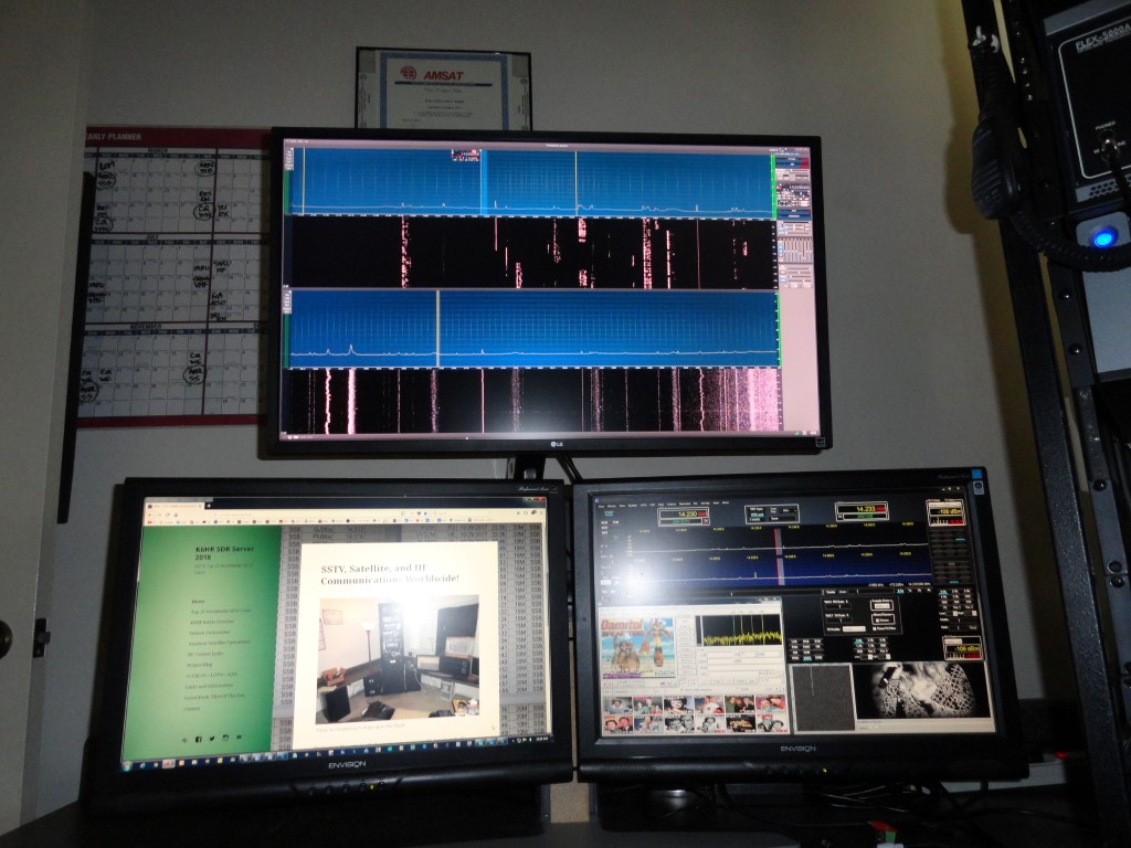
The PC monitors are in place, look great, and exhibit no RFI at full output. The operating position is fully tested and ready for the contest.
I decided to try a 4K UHD monitor and selected the LG 32UD59-B (top) and it looks fantastic!
View from the operators chair! Everything within reach and easy for me to see.
The few minor problems that remain will be addressed after the contest. For all intents and purposes, this project is complete. I may decide to upgrade the PC monitors in the near future, but for now the station hardware is complete.
Now it’s time to OPERATE!
-P.S. 02-23-18: I was doing some testing with the data cable connected to the recently installed AT-AUTO, and the tuner works as expected. I was able to work KB3RHR and K7KPH and both gave me great reports.
The AT-AUTO arrived safe and sound in spite of a loose packing job. By the time the box arrived it was all “rounded out”. This is what happens when you use a light gauge box for a heavy item, and the item is ‘loose’ inside. Yep, you guessed it…the box was full of styrofoam ‘peanuts’. Hey, it was a happy ending, the tuner works as expected so far. There are a couple of cosmetic differences that I imagine have to do with the different production runs. Overall I am happy with this purchase. More info available at the Kessler Engineering website.
AT-AUTO Data Cable
The data cable was scheduled to arrive today, but did not. So I say ‘so far’ because I could not test the data port tonight, but I’m sure it won’t be a problem. The coax cables arrived on time because the eBay seller shipped them on Saturday! Hat’s off to “WifiExpert” on ebay! Highly recommended!
Palstar AT-AUTO – The perfect tuning solution for my shack!
The AT-AUTO was one of the last pieces I needed to complete my 2018 station overhaul. I now have near perfect SWR everywhere. The Expert 1K-FA is a great amp, but the internal tuner only matches up to 3:1 SWR. I had issues with antennas being out of range of the 1K-FA internal tuner, and resolved ALL issues via the AT-AUTO.
Fully Automatic Tuning – QRO
I cleared the memory and trained the tuner on all bands, then did the same with the tuner in the amp. The result is a perfect match on any frequency, on any antenna, and tuning is fully automatic! I’m very happy to have this in place for the ARRL contest.
The AT-AUTO ‘s will follow the active TX slice on the radio, and enable the operator to concentrate on the work, and not be concerned with making errors when changing bands etc.
Todays work included installation of the SO2R RX Loop Antenna and associated devices. The W6LVP relay will provide switching for the SO2R RX Loop Antenna. I’ll also install some front end protection.
The SPE Expert 1K-FA amplifier allows connection of two transceivers, four antennas, and, an SO2R RX antenna. When the OP is transmitting on radio#1, radio #2 is connected to the SO2R RX antenna. This enables the operator to listen on radio #2 while working the latest DX on radio #1, and vice versa.
SO2R RX Loop Antenna for low noise
Operating in SO2R mode presents the possibility of overloading or damaging the sensitive RX front ends of the two connected transceivers. The 1K-FA manual warns of this possibility and cautions the user about antenna separation and it is suggested (and makes the most sense) that receiver front end protection devices be considered.
The Flex transceivers have built-in RX protection, but adding an RX front end protection circuit offers one more level of protection.
From the May 2014 QST article:
The RXFEP uses multiple devices to soft limit input signals starting at –1 dBm and outputting a specified maximum signal level of +10 dBm to the re-ceiver input.While manufacturers do not generally specify the maximum safe input levels for their equipment, it is worth noting that ARRL Lab re-ceiver dynamic range tests include input signals as high as +10 dBm, and we haven’t lost one yet.
An obvious place to install this device is at the RECEIVE ONLY ANTENNA port of a receiver. By having it as close to the receiver as possible, any pickup on the cable between the device and the receiver is minimized. There is another potential application in some installations, however. Some receive-only antennas include a remote preamplifier at the antenna termination. A protector at the remote preamp input would also be appropriate, although consideration should be given to the preamp input impedance, with a transformation to 50 W, if needed. If there is a long coax run from the remote preamp to the receiver, a second protector could be used at the receiver in case of loose coax connectors or other shield impairments. It should be obvious, but I’ll say it anyway. This unit cannot be used on any antenna feed that is also used for transmitting. Damage to both the unit and the transmitter would be likely consequences.
The low noise RX Loop Antenna is hereby considered a major station improvement!