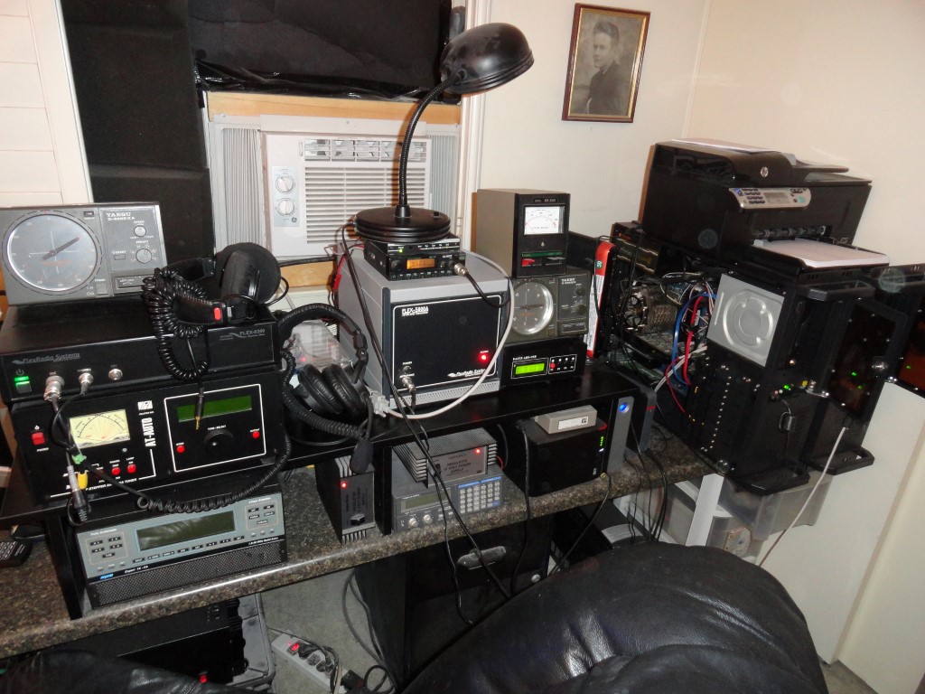
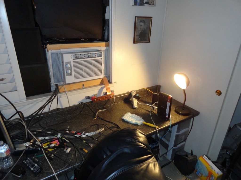
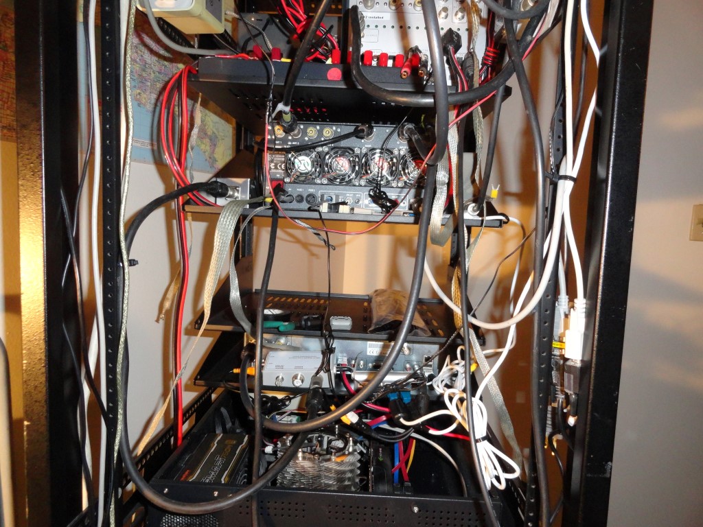
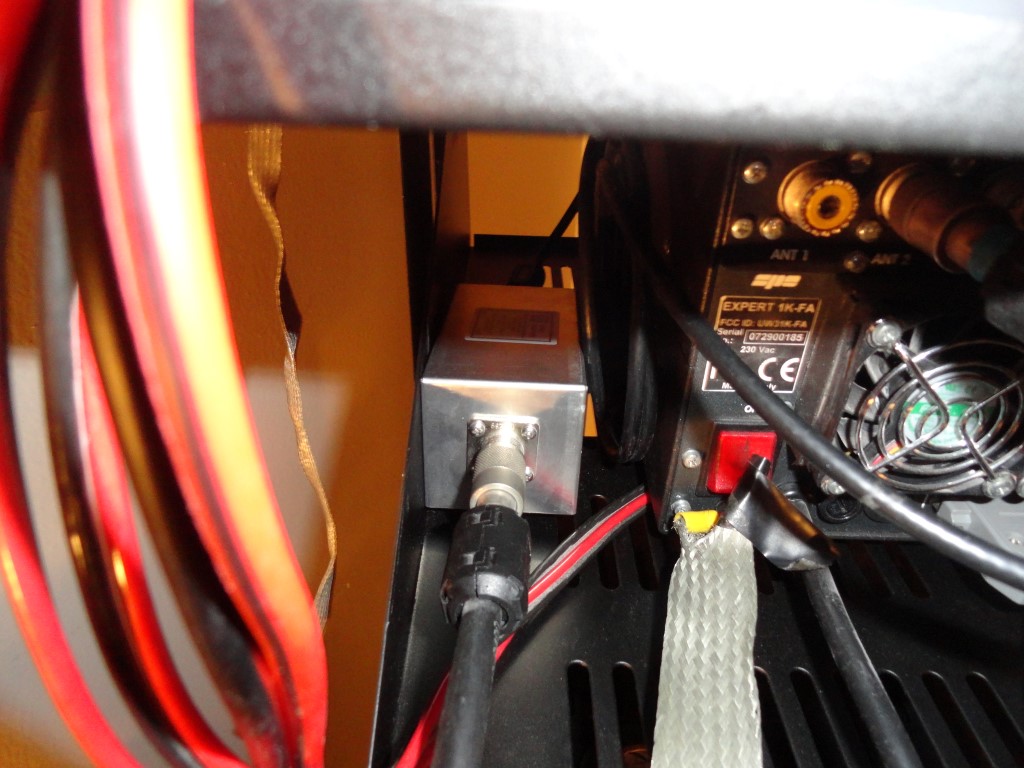
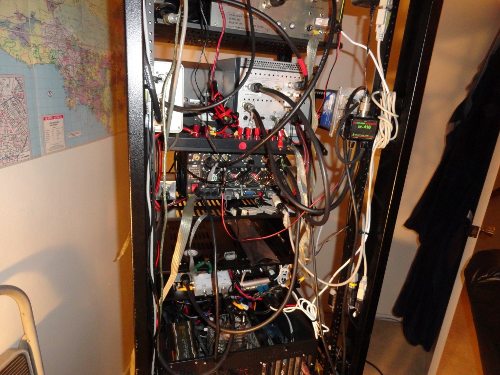
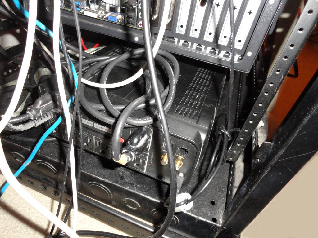
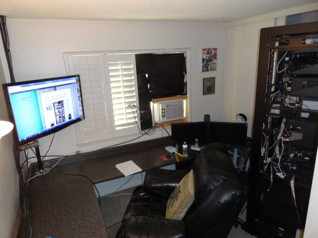
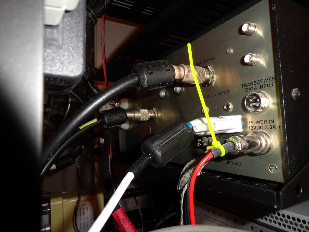
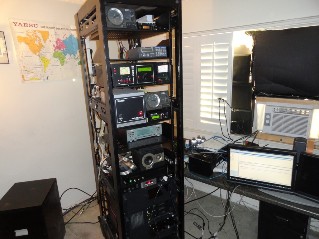
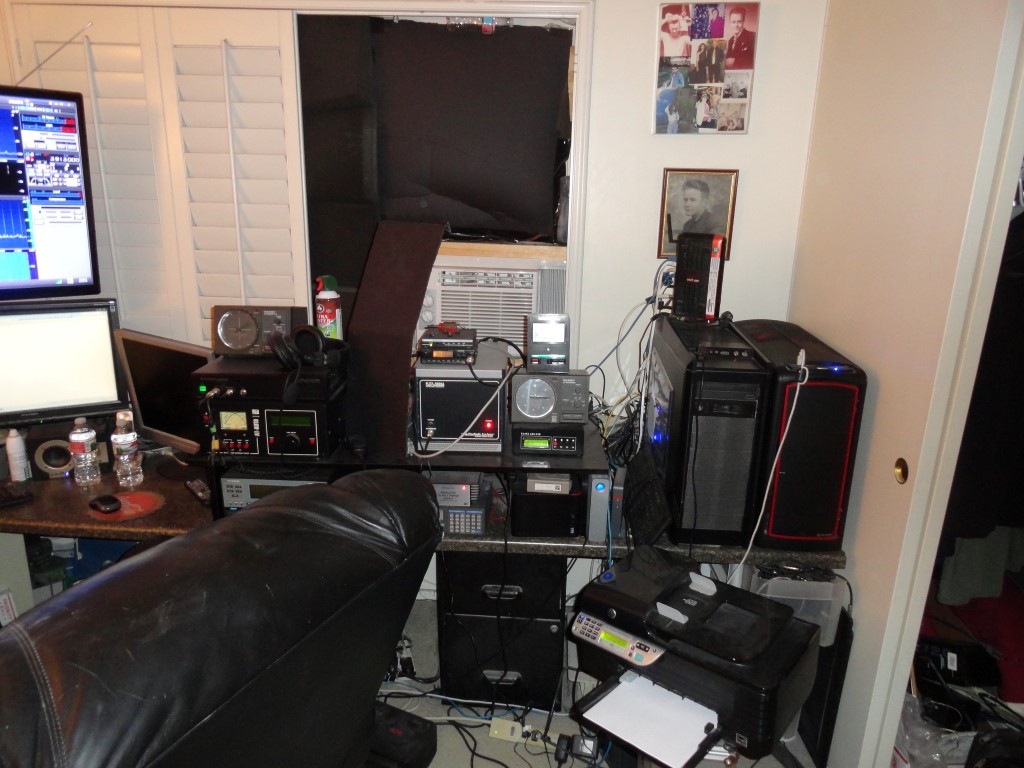
Well, as you can see, the shack is overdue for a seriously needed overhaul! Follow along as I tear this all down and rack mount it. It’s a BIG job, and it will have to be finished before March 3rd. The Rack Mounting Project is officially underway!
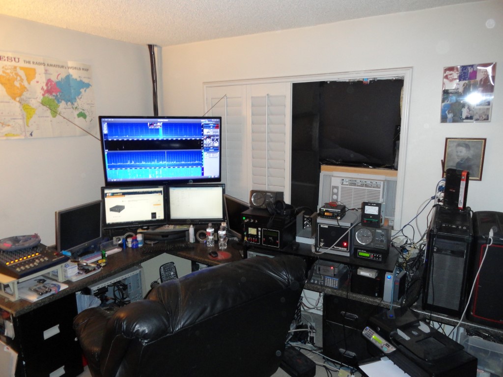
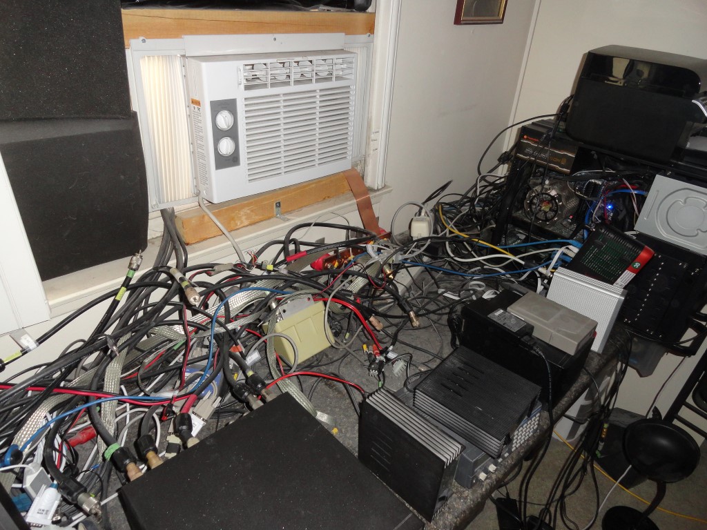
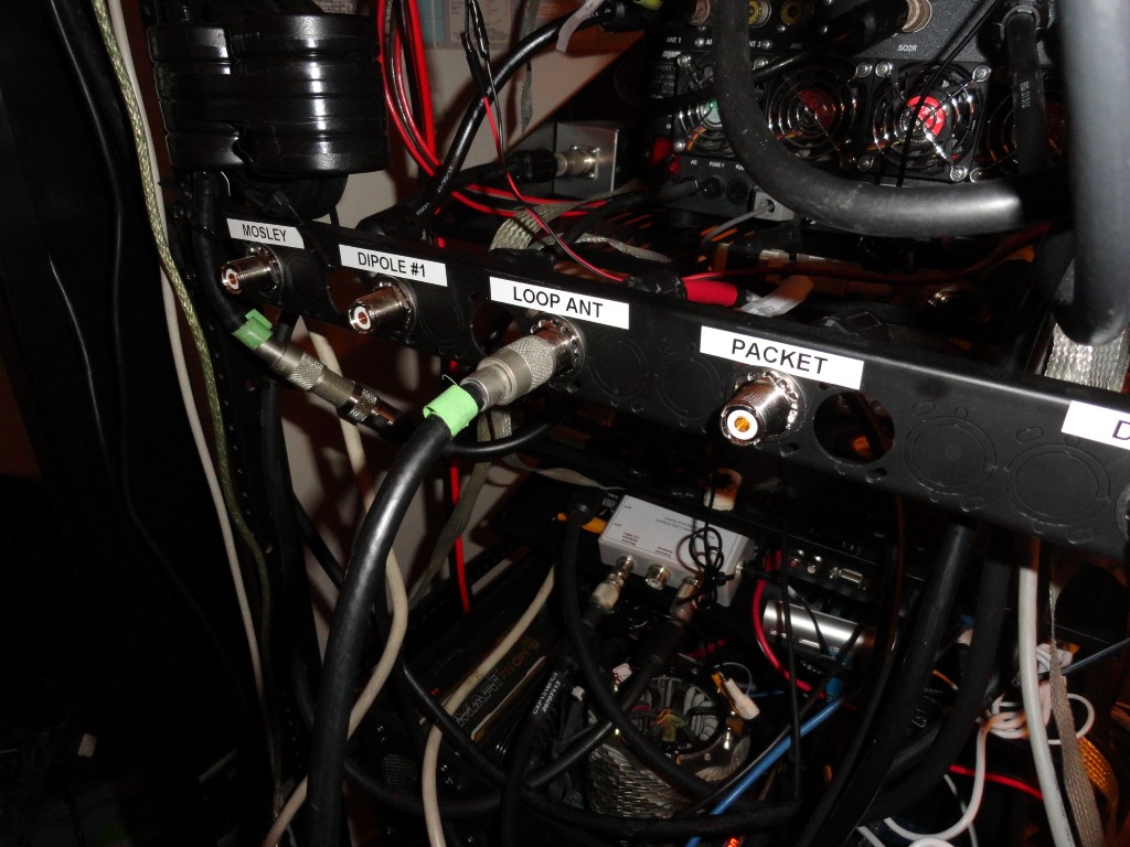
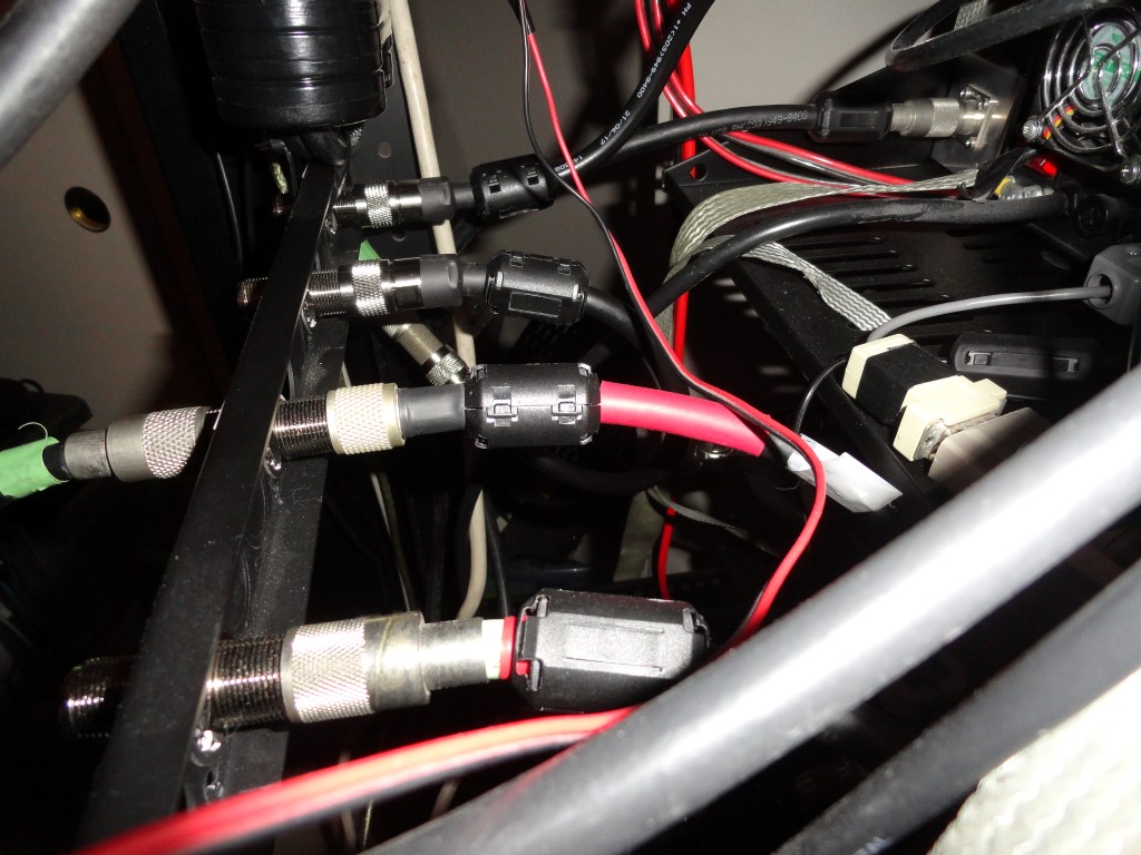
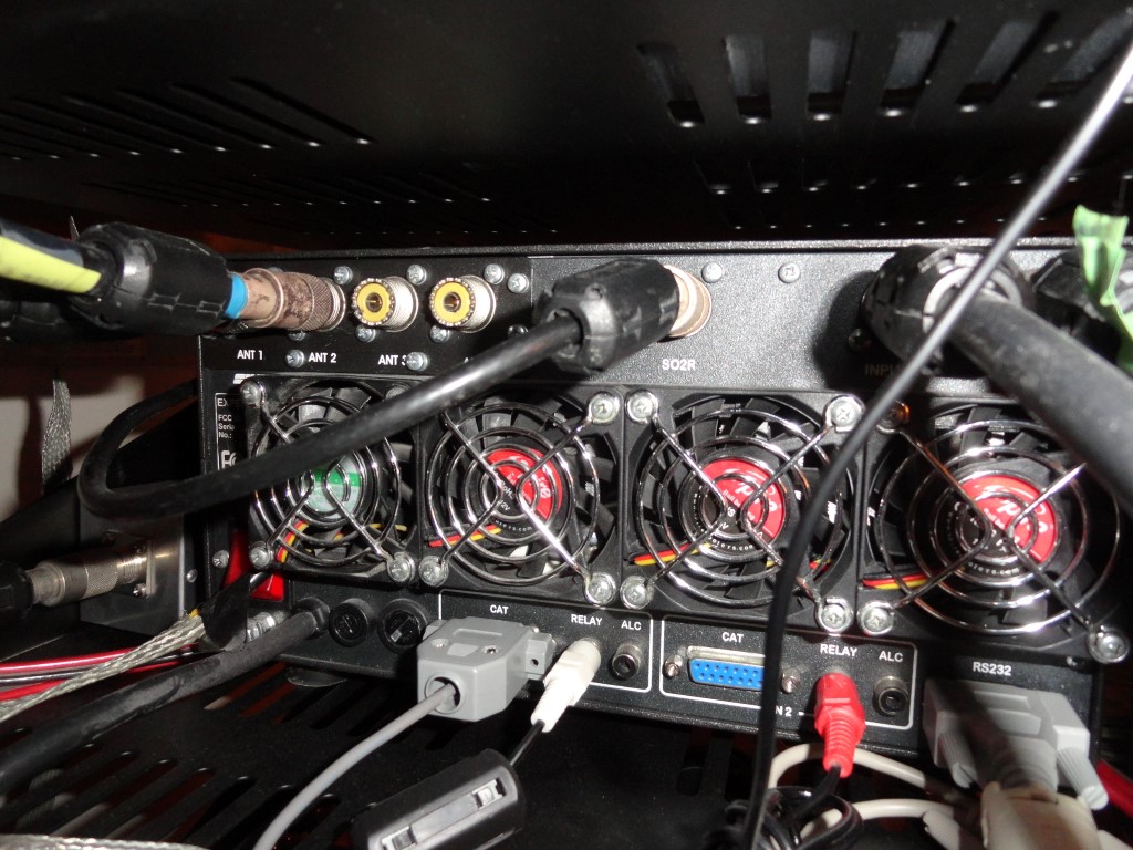
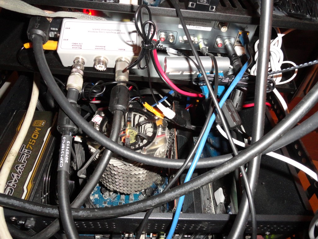
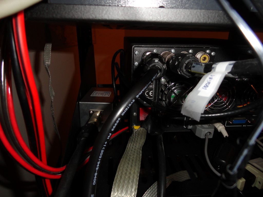
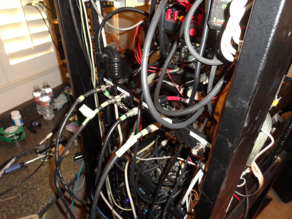
There’s no room for any additional equipment, and trying to work with any of the cables behind the current setup is nearly impossible! I tried adding a TV riser so I could stack more gear, but I still ran out of space.
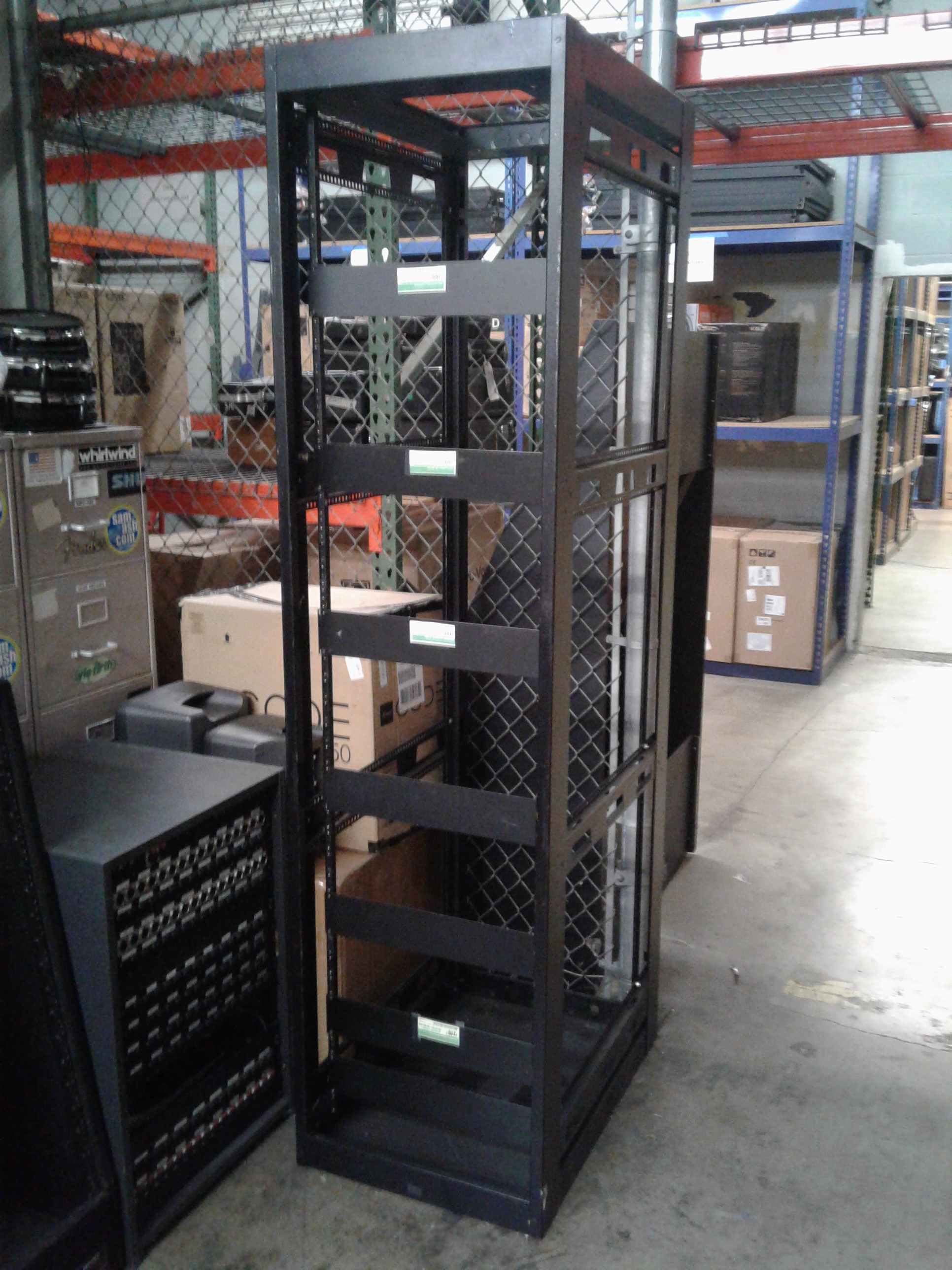
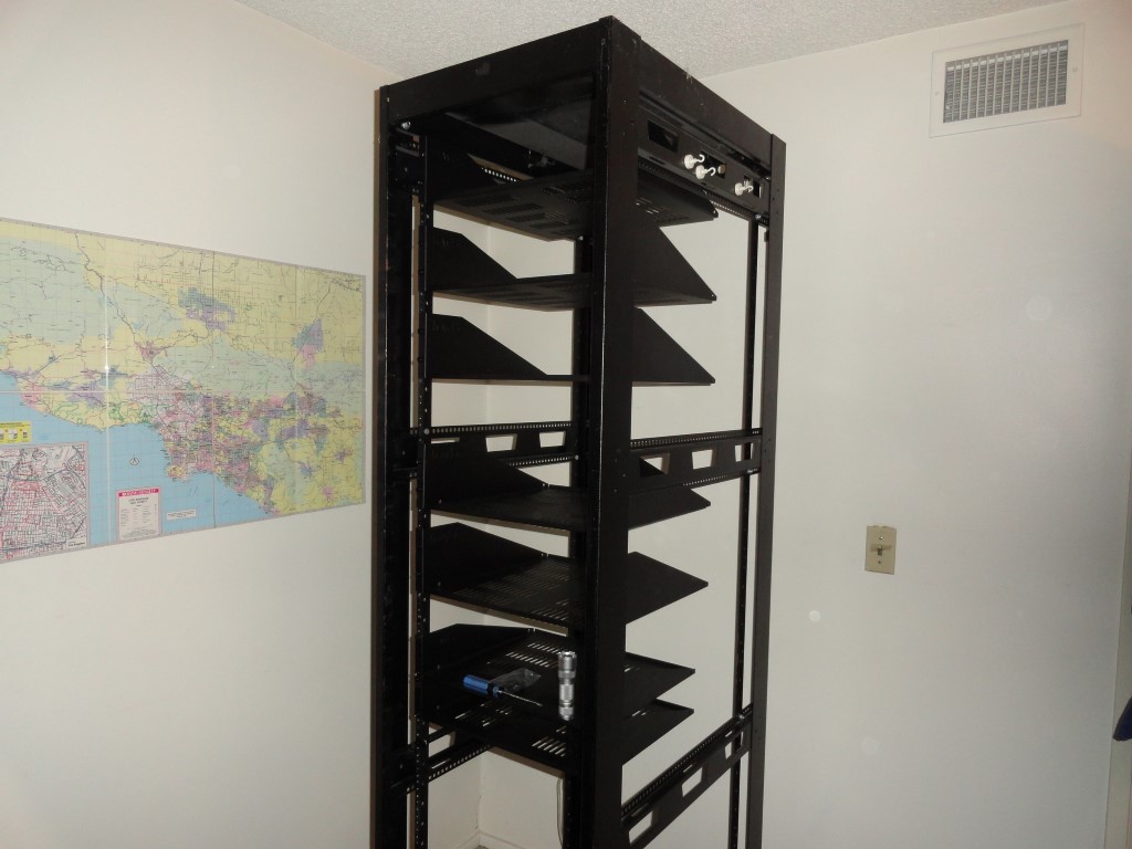
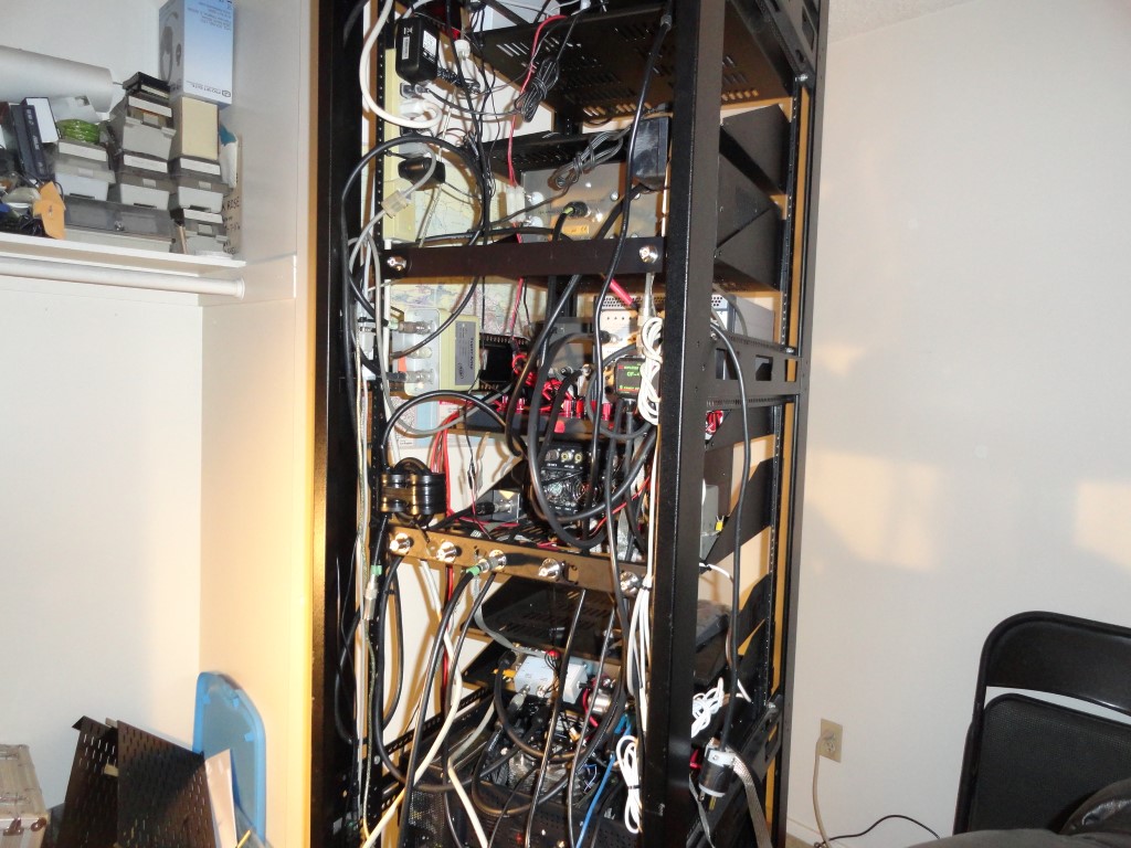
A Nice Save!
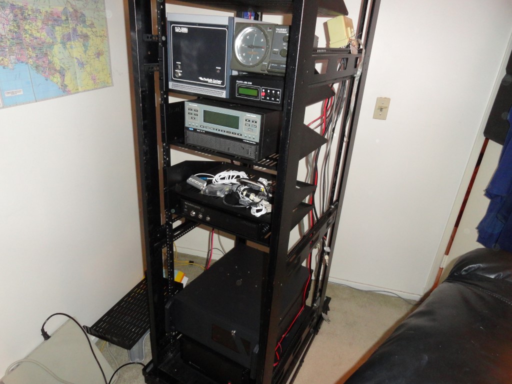
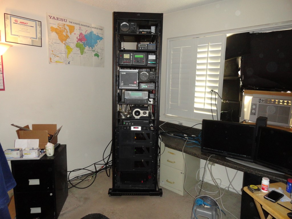
I came across this 44U server rack as it was heading for the scrap heap, and got the idea to “go vertical” and transform my radio room into a much more productive space. The idea for the rack mounting project was born!
Yes, this would involve significant planning…<grin>
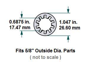
I started with a measuring tape.
- Will this rack even fit in my room?
- Could my gear fit in this rack?
- How many rack spaces will I need exactly?
- What hardware will I need in order to mount everything?
- How will I move it around?
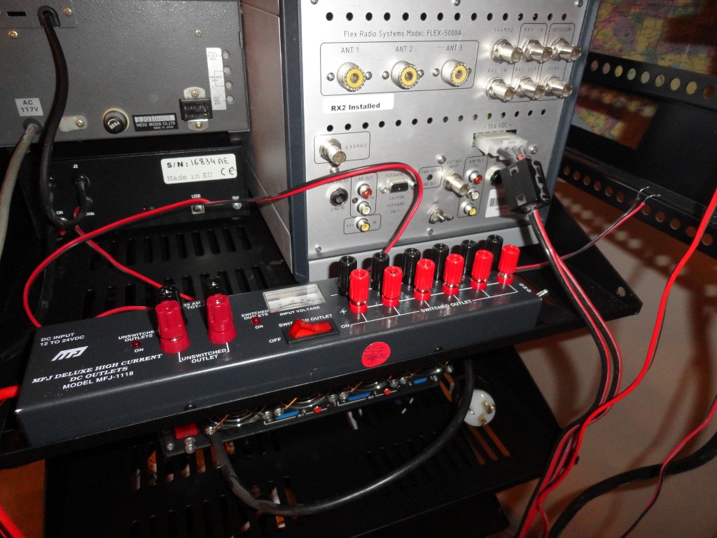
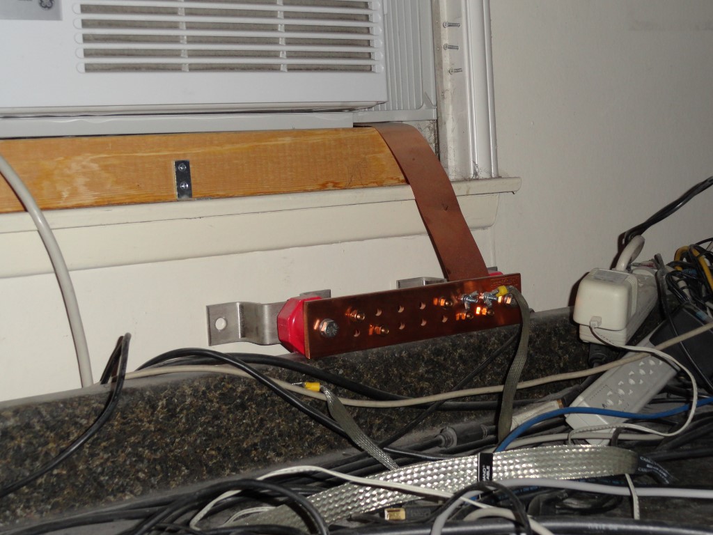
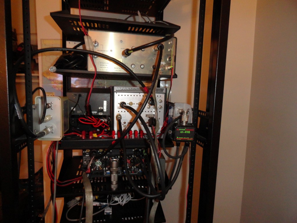
- There are Grounding and DC distribution considerations
- Vertical Layout Planning
Once I could see all these numbers were falling into place, I made arrangements to get the rack dropped off. I got the idea sometime in September or October and started measuring. I had the rack delivered in early November, and started ordering all the parts.

 Advance Planning
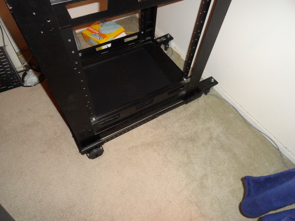
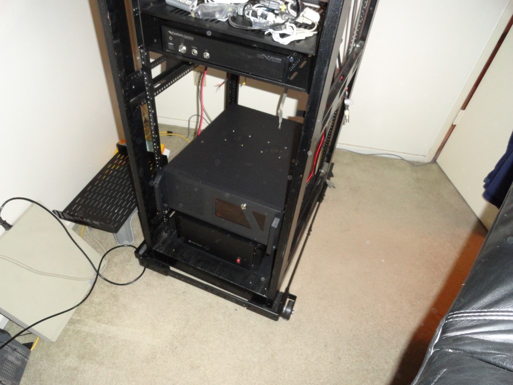
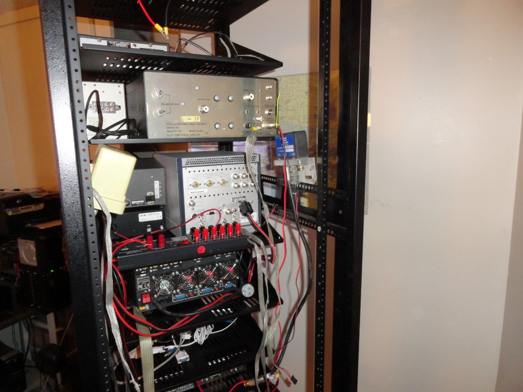
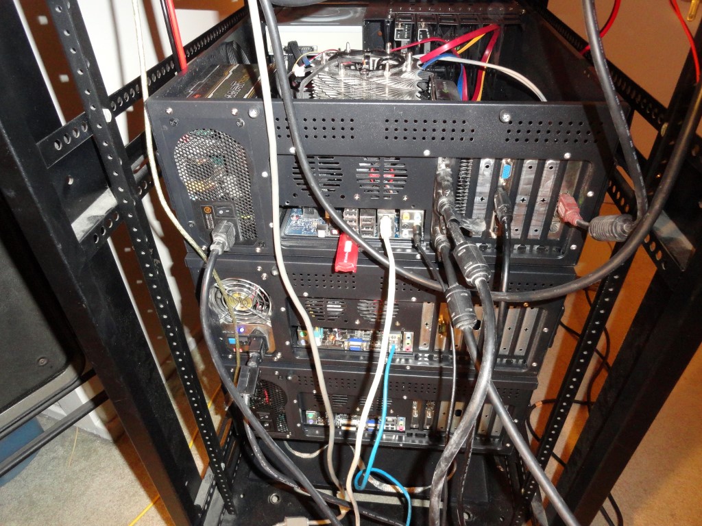
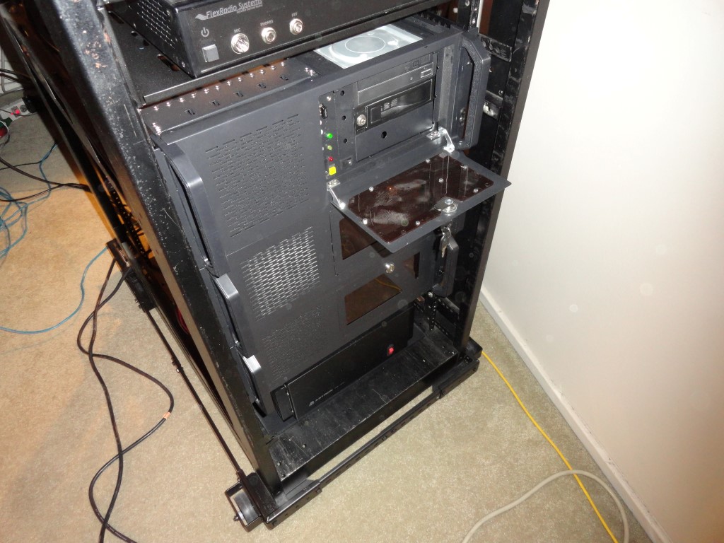
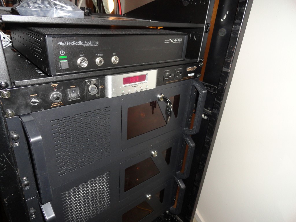
At this point I’ve resolved the mobility issue (Craftsman Mobile Base), rack mounted all 3 PC’s and removed all the unwanted furniture and clutter from the radio room so I’ll have room to start the build.
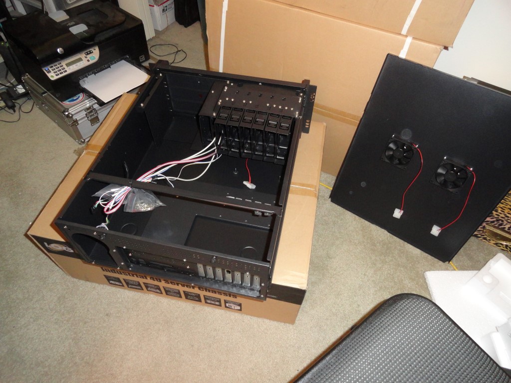
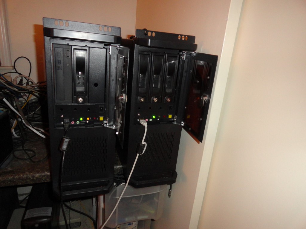
The PC’s went into the rackmount cases without a hitch. I’ll mount them once the shelves arrive.
Today I took a second look at WordPress and decided to install it on the web server here in the shack. It was easy to install, and appears to be up and running OK.
I plan to document the steps taken to complete this rack mounting project as I go along, while at the same time learning WordPress and planning the repair bench that will follow the rack conversion. Right now the rack is still in the garage and will likely stay there until after the holidays.