Rack Mounting Project

Corsair Voyager GTX 512GB USB 3.1

It’s like having an SSD on a stick!

I just picked up a CORSAIR Voyager GTX 512GB USB 3.1 Premium Flash Drive Model CMFVYGTX3C-512GB. Initial testing shows it lives up to it’s claims of SSD like read/write speeds.

Corsair Voyager GTX
Corsair Voyager GTX 512GB USB 3.1 Flash Drive @ USB 3.0

Corsair Voyager GTX 512GB USB 3.1 Flash Drive

The benchmark test results shown above actually exceed those published by Corsair. They’re advertising speeds up 440 MB/s. This test was run on an i7-8700K CPU 32GB RAM using a USB 3.0 port.

From the Corsair Website:

Experience portable USB storage with the speed of a solid-state drive.

High-speed 3D NAND memory unlocks read speeds up to 440MB/second and write speeds up to 440MB/second, letting you copy even large files in seconds.

Available in 128GB, 256GB, 512GB and massive 1TB capacities, so you can carry all your data, wherever you go.

Premium rugged zinc-alloy housing with aluminum accents protects your data in style.

Optimized for USB 3.1 Gen 1, USB 3.0 and USB 2.0 for future-proof and backwards compatibility.

Format, partition and optimize drive performance with CORSAIR SSD Toolbox software.

Works on Windows 7, 8.1,10, macOS and Linux with no driver installation needed.

Other system drives for comparison

Samsung EVO 860 SATA II
Samsung EVO 860 on a SATA II controller (That’s a shame!) on an older Intel motherboard.

ABOVE: Benchmark for Samsung EVO 860 on a SATA II controller running on an older Intel DP55WG motherboard.

2TB Samsung EVO RAID
2TB Samsung EVO RAID 2X 1tb evo in RAID 0 on a SATA III Controller

ABOVE: Benchmark results for Samsung EVO 860 (2x 1TB RAID o Array) on a SATA3 controller.

Intel 660p Series M.2 2280 1TB PCIe NVMe 3.0 x4 3D2, QLC

ABOVE: Benchmark results for the Intel 660p Series M.2 2280 1TB PCIe NVMe 3.0 x4 3D2, QLC main (C:) drive for Windows 10 O/S

All the more reason to have the fastest USB stick available.

Back To The Front

HF Barefoot FT4 and FT8

Working the World with 86 Watts!

It has been 10 months since my first FT8 contact back on 2/15/19. Working HF barefoot in FT4 and FT8 modes. The dedicated Flex 6500 puts out about 86 watts into the CHA-250 vertical.

38 DXCC Entities and WAS

As of today 12/14/19 I’ve made 1,433 ‘FT’ contacts comprised of all 50 US States and the following DXCC entities:

Canada, Japan, Mexico, Spain, Cuba, Belize, Asiatic Russia, European Russia, Australia, Puerto Rico, New Zealand, Canary Islands, Venezuela, Fiji Islands, New Caledonia, Cayman Islands, Argentina, South Africa, Belgium, Ireland, Azores, Hawaii, Samoa, Mauritania, Alaska, Ecuador, Chile, Dominica, Costa Rica, Trinidad & Tobago, Aruba, South Cook Islands, El Salvador, Lesotho, France, San Andres Island, Columbia, and French Polynesia.

Nice Results for Part Time QRP OPS

I’m very pleased with the results I’m getting with the 6500 HF barefoot FT4 and FT8 operations. 1405 of the contacts are in FT8 and 28 so far in FT4. I installed WSJT-X v 2.1.2 on 11/28/19 and find that there is far less activity on FT4 than FT8. Nonetheless I will continue to work it as often as possible.

It will be interesting to see sometime down the line what kind of results I’ll get using the Mosley and the amplifier. The low power (QRP) operation is so much fun, I plan to keep it in place for the foreseeable future.

Perhaps a 2020 upgrade candidate to consider might be an amplifier for the Flex 6500…

WSJT-X implements communication protocols or “modes” called FT4, FT8, JT4, JT9, JT65, QRA64, ISCAT, MSK144, and WSPR, as well as one called Echo for detecting and measuring your own radio signals reflected from the Moon.  These modes were all designed for making reliable, confirmed QSOs under extreme weak-signal conditions. 

Back To The Front

OT: 1956 Fender Stratocaster

If you’ve ever dreamed of owning or playing on an old Fender Strat you may find this story interesting. This instrument is a great example of the so-called Holy Grail of electric guitars! Here’s how I came in contact with a very well preserved 1956 Fender Stratocaster.

I work in a music store where we buy and sell musical instruments of all kinds. It was just another day in the neighborhood one day, when a woman stopped by with her fathers guitar looking for some advice.

When I saw the case she was carrying in, I immediately knew it would be something exciting. In her hand was an ancient Fender guitar case. She explained her father was the original owner, and the guitar had spent many years “under the bed” and had not been played much. Her Dad had recently passed away and she had decided to sell the guitar.

1956 Fender Stratocaster
Exciting moment we open the case!
1956 Fender Stratocaster
The ancient Fender nameplate!
1956 Fender Stratocaster

She told us she was in the process of ‘shopping it around’ taking offers. We told her the guitar was rare and very valuable and she should be very careful selling it. She told us she had already done some research on it, and had a pretty good idea what a fair offer should be.

Time to call the boss!

This is the Holy Grail of guitars! We can’t let her leave and possibly sell it to someone else! It’s time to call the boss and make the sale happen now! We took these pictures and sent them to the owner of our company and he had a fast and simple reply: “Ask her how much she wants to stop shopping it around right now!”

We did, and an agreement was quickly reached.

Holy Smoke! We are about to purchase a super clean, all original, 195o’s Stratocaster! I don’t have to tell you this is a once in a lifetime experience for the employees in our store!

taking a ‘hard look’

On the surface everything looks perfect and we are very excited to have a look inside.

1956 Fender Stratocaster
1956 Fender Stratocaster #15974
1956 Fender Stratocaster
1956 Fender Stratocaster – Remarkable condition!
1956 Fender Stratocaster
A look behind the pickguard! So far so good!
1956 Fender Stratocaster
Untouched original electronics!

The Moment of Truth!

1956 Fender Stratocaster
The Moment of Truth! October 1956!

This guitar was assembled in October 1956. Certified Vintage!

Case Candy Included!

Complete with Case Candy! “Ash Tray, Tremolo Bar, and Original receipt!

Inside the case we found the tremolo bar, the chrome “ash tray” bridge cover, some old cables, the case keys, and the original purchase receipt!

It cleaned up real nice!

1956 Fender Stratocaster
It cleaned up real nice! Soon to be on it’s way to a new owner!

How about Dad’s amplifier?

Say what? Dad’s amp you say!

1956 Fender Tremolux
1956 Fender Tremolux also in great condition!
1956 Fender Tremolux
Truly remarkable condition for its age!
1956 Fender Tremolux
The original Jensen speaker was found to be blown. But the amp still worked great!

Back To The Front

Flex 6700 Timeout Error!

Flex 6700 Timeout During the CQ WW WPX SSB Contest!

Flex 6700 Timeout
Flex 6700 “Timeout” Error displayed after power cycle.

Another prime example of what I call “The Luck of the Irish”! During the CQ WW WPX SSB contest today I encountered the Flex 6700 Timeout error.

The radio lost its connection to the PC, and when I attempted to restart it, it failed to boot. After power cycling, the “Calibrating” phase took much longer than usual, and resulted in the “Timeout” message shown above.

Other users with Flex 6700 Timeout

A quick check of the Flex Radio Forum showed others with the same problem needed to return their radios for service. I promptly opened a Help Desk ticket, pulled the radio, and boxed it up. Based on the forum comments, I’m pretty sure they will tell me to send it back. This has previously been reported as a hardware issue by other users. So it appears the timeout issue goes back a few years.

From Tim (in the Flex Forum 2 years ago):

“The original FLEX series radios had only one CPU.  The FLEX-6000s have multiple CPUs and when the system boots it has to perform a series of initialization procedures to ensure the subsystems are communicating with one another.  Part of that is ensuring the correct timing”.

Flex 6500 to the Rescue!

I just did a quick change over to my 6500 and I was back in the thick of the contest in no time flat!

Flex Radio: Famous for Great Service

I’ve had repair work done under warranty before, and have thus far had nothing but a positive experience. However, I am no longer under warranty, so it will be interesting to see what it’s going to cost to repair this problem!

More on this later…

UPDATE: 3/30/20 Flex Service Responds!

Maybe I was too quick in boxing it up!

I received a reply from Tim Ellison the first thing in the morning on the following business day. After performing a full reset, the radio still displayed “Timeout”. Tim went on to explain that the 6700 utilizes an SD card to store the radio’s firmware, and he believes the failure may likely be in the SD card.

Tim also included an instruction sheet on the procedure for changing out the suspect SD card. He suggested that if I was comfortable changing the card my self, there would be no need to return the unit to Flex for repair. The installation guide showed this was well inside my “comfort zone”, so Tim put a replacement SD card in the mail for me. Fantastic!

Great News! (If the SD Card Solves it!)

As far as I’m concerned, I’m thrilled at the idea that I may not need to ship the radio back. I’m confident that Tim and the folks at Flex Service have seen this problem often enough to know that replacing the SD card will fix it. A simple fix that GREATLY reduces my downtime!

Flex 6700 “Timeout” On the Bench

Flex 6700 on the bench
Flex 6700 “Timeout” Error on the Bench

Pictured above: The Flex 6700 with the bottom panel and RF Isolation Cover removed.

Flex 6700 "Timeout" Error
Flex 6700 view showing the SD card socket. Ready when the new SD card arrives!

It should be a simple fix and minimal downtime. Did I mention how happy I am that I don’t have to ship it back?

More on this once the new SD card arrives…

Update 04/04/20: Problem Solved!

Flex is really on top of their game in the service dept.! The first SD card Tim sent appeared to be lost by the USPS. That is, the tracking had not updated after the item was mailed out. Again, first thing in the morning, the next day, I received an email from Tim at Flex stating that he had noticed the tracking had not updated, and fearing the item may have been lost by the USPS, he sent me out another one!

Who does this?…Flex Radio does! I consider this to be “over the top” quality of service from Flex. I deal with a lot of vendors on a daily basis, and many of them are very good, but none of them compare to Tim at Flex. I’m very impressed! Did I mention how happy I am that I did not have to ship the radio back? Hi Hi!

I installed the new SD card and the radio came right back to life!

THAT’S WHAT I CALL A HAPPY ENDING!

Back To The Front

Comet CHA-250B Ground Rod Installation

A Quick Modification!

I recently read several articles about CHA-250B installations and realized I had not grounded the antenna as some of the articles had suggested. The CHA-250 owners manual doesn’t indicate a ground connection. I was following the owners manual when I installed the antenna. I was curious to see if it would have any effect on performance. So I bought some supplies and started the Comet CHA-250B ground rod installation. I first realized I was missing the ground connection when I found this schematic on the G8JNJ website:

CHA-250B Balun Schematic
CHA-250B Balun Schematic showing ground attached to coax shield.
CHA-250B Grounding
CHA-250B Grounding. I used hose clamps, as I did on all my other coax ends.

The ground wire is connected to the coax shield using a hose clamp. The copper wire under the clamp is doubled over, to make better surface contact. An idea I got from K3DAV’s website.

CHA-250 Ground Rod
The CHA-250 Ground Rod has two hose clamp connection points (bottom and middle)

All connections to the copper ground rod were doubled over, and clamped, to create more surface contact I’ve had success with the clamping idea, so I used those clamps again.

Results!

I run FT8 using a Flex 6500 barefoot into the CHA-250B. It puts out 86 watts. The CHA-250B does not disappoint! Over the past two days I have worked JA, UA0, 9Y, SP, OH, VK, UT, and KH6! Just to name a few! I now have thousands of FT8 contacts across 6 bands!

The antenna is a bit quieter, noticeably so on 30m, and the SWR is roughly the same on all bands. I can’t claim any big improvements. Static charge build-up, caused by high winds, will go to ground. Installing the Comet CHA-250B ground rod was definitely a worthwhile endeavor.

Update: 06/18/20

Since grounding the CHA-250 I’m noticing European stations in the FT8 monitor panel. Prior to this, I’d rarely seen any calls from the EU. Either conditions have suddenly improved, or adding the ground has made a significant improvement. With all the complaints I hear on the air about conditions, I have to believe adding this ground to the CHA-250 has caused improved performance. I’ve worked all through Europe since installing the ground.

Back To The Front

JNOS UPTIME RECORD!

A JNOS Uptime Record at K6HR

JNOS UPTIME
JNOS UPTIME

JNOS UPTIME has never been anywhere near this number! A JNOS Uptime record has just been set!

It’s been running for over 6 months at this point. How long will it go?

What is JNOS?

From Maiko’s JNOS Website:

JNOS Is a monolithic software application for amateur packet radio (ax.25) and ip networking. JNOS’ origin traces back to Phil Karn’s KA9Q/NOS software. Widely considered as the foundation of TCP/IP over radio.

In fact, NOS was the linux of it’s time, transforming simple DOS machines into multiuser/multitasking TCP/IP environments. Also worth noting are MFNOS by Barry Siegfried (K2MF), TNOS by Brian Lantz (KO4KS), and WAMPES by Dieter Deyke (DK5SG/N0PRA) – each (including JNOS) taking ideas and bits and pieces from the others.

JNOS is first and foremost a router for ax.25, netrom, and ip protocols – ip over rf is possible by encapsulating the ip in ax.25 frames. The original JNOS v1.11f and earlier distributions do not support a lot of the features we enjoy in todays version.

Features currently available in the JNOS 2.0 distribution started back in October of 2004. Over the years, JNOS 2.0 has made it to 4 different platforms – DOS, Linux, WIN32, and Mac. Linux has been the primary development platform for years now.

Back To The Front

K6HR Contest Station Block Diagram

SO2R HF Contest Station Configuration

K6HR Block Diagram
K6HR HF Contest Station Block Diagram

Expert 1K-FA: At the Center of SO2R Ops

The Expert 1K-FA does all the antenna switching automatically. Fully automated, and carefully programmed, the 1K-FA greatly reduces the chance of user error. The K6HR Contest Station Block Diagram makes this SO2R setup a bit easier to understand.

The transceiver is a FlexRadio 6700 featuring two Spectral Capture Units. I utilize the two SCU’s as “two radios”, each with its own amplifier, tuner, and antenna. I designate ANT1 as the Mosley TA-33-JR-NW (for all HF bands 20 meters and above) and ANT2 as my 130ft Height Compromised HF Dipole for frequencies on 30 down thru 160 meters. Low SWR across all amateur bands!

The cool trick is the operator can move freely through the bands and operate at will via either radio. The 1K-FA’s foolproof switching ensures the TX radio will get the correct TX antenna every time. The second radio, in every case will be connected to the wideband RX loop antenna.

Data Driven via Flex USB

The Expert 1K-FA and the Palstar autotuners operate based on frequency data received from the radio. The 1K-FA and the AT-AUTO autotuners follow the radio in realtime as the operator changes frequency.

The operator only needs to turn the ‘tuning dial’ and press the PTT!

LP-500 Station Monitor

I have installed the LP-500 station monitor with 4 sensors. You could say it takes the guesswork out of getting good reports!

LP-500
LP-500 Linearity Check

Leveraging the four sensors of the LP-500 Digital Station Monitor, I can ensure both amplifier channels are operating at full output, with the lowest SWR, and best linearity at all times.

Back To The Front

Database Crash!

A huge headache! But I got it all back!

On Monday July 27, I came home to discover that both of my WordPress sites were offline due to a power incident. Browser connections to the server returned “Error establishing a database connection” for both sites. I also found the MySQL server was not running, and could not be restarted. In addition, apcupsd was reporting “Unacceptable Line Voltage Changes” as the reason for the most recent UPS event. I’d had my first database crash.

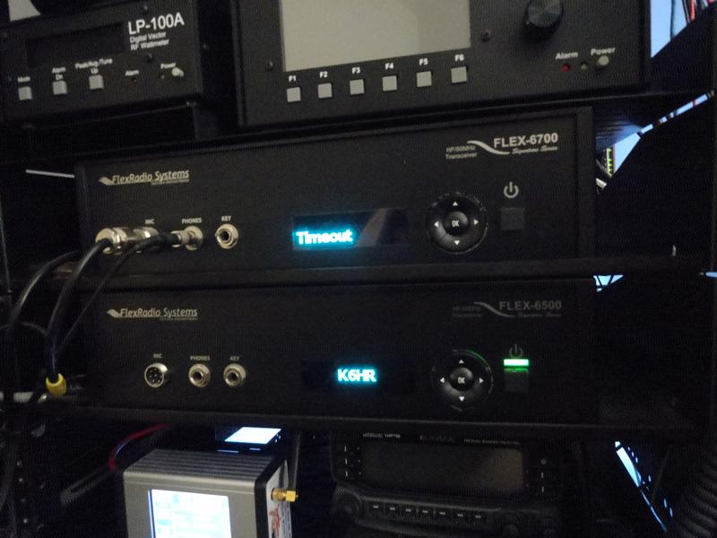
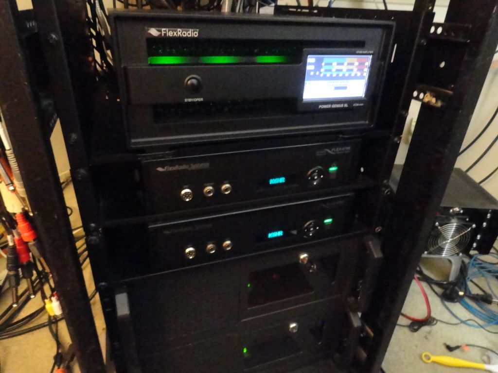
Three other machines in the shack were found running, but I could see they had all restarted. This is nothing new in Norwalk CA. Even though each machine has a dedicated UPS, I continue to have service problems with the local utility company. In this case it looks like it was a surge, not a loss of power, and the bounce was enough to corrupt the database.

I’m lucky no hardware was affected this time.

No Problem…I have backups of everything.

My sites use the UpdraftPlus Plugin for creating backups. I create a backup whenever any changes are made to a site. It’s fair to say I have ‘backups up the wazoo’. I can beat this database crash!

So UpdraftPlus did it’s job of creating backups. but I soon realized that you can only restore from a working WP site, that has the Updraft plugin installed. In addition to UpDraft backups, I had a copy of the mysql data directory containing the .ibd files of the individual database tables, so I felt my chances were pretty good I would get everything back.

So, I reinstalled WordPress with a fresh database, using the same database name as the site being restored, installed Updraft, and let rip on the most recent backup…(July 20, 2020)

Updraft Restore Failed (missing files?)

This was a major setback.

My mother used to say, “Don’t keep all your eggs in one basket”, and that was exactly what I had done with the Updraft backups. I had failed to realize the need for mysqldump .sql backup files, and hadn’t created any outside of the UpDraft plugin. Big mistakes. Like it or not I have a ‘learning opportunity’ of how to recover from a WordPress database crash.

Another problem was the InnoDB ibdata1, ib_logfile0, ib_logfile1 files were also corrupt, so I could not repair the Inno database in the usual way. This left me with only the .ibd files for the database tables. If they were not also corrupt, they might just be my last chance at recovery. A somewhat scary position to be in when years of work are on the line. I learned my lesson right there!

Recover mysql database from .ibd files?

What do I know about extracting sql from an InnoDB file? Absolutely nothing!

But my research showed it could be done.

After trying various methods found online, I zeroed in on the info contained in this article. It quickly became apparent that the article was written for folks with a lot more SQL knowledge than I currently possess, so there was much I didn’t understand, and had to research my way through.

Soldiering on, I was able to successfully extract the 12 base WP database tables into table.sql backup files using the DBRecover software. I learned a lot in the process. I was now ready to import the 12 base WP database tables.

They imported just fine, but were not enough to get the site back online. There were a total of 52 .ibd files. 12 ‘base’ files, and 40 .ibd files supporting the installed plugins. The remaining 40 .ibd files would all need to go through the same extraction process. So I figured I’d be at it for a least another week or so.

Not the whole problem…

As research continued and I went on to carry out some other tasks, I discovered there had also been some damage to the filesystem, the damage was not limited to the database crash. So I decided to rebuild the server with a clean installation of Ubuntu Server 20.04.

After copying everything I would need to reinstall, I wiped the old server and did the clean install of Ubuntu 20.04.

My big break!

Once the clean new OS, and fresh install of WordPress were complete, I figured it was worthwhile to try the UpDraft restore one more time. What if something in a corrupted area of the filesystem had been preventing UpDraft from operating properly? So I installed the UpDraft plugin, chose the July 20, 2020 backup, and let it rip…

BOOM! Just like that!

Much to my delight, that was exactly the case! The restore was successful! Holy smoke! I almost couldn’t believe it! Everything restored perfectly! What a relief! OK UpDraft, you have a new brand ambassador! Hi!

LESSONS LEARNED: NEW BACKUP PLAN
  1. Create a mysqldump ‘database.sql’ backup file after making any site changes.
  2. Save a copy of the /html directory (or at least the wp-content directory)
  3. Copy of the most recent ‘UpDraft’ backup.
  4. Store backups across all available storage devices. NAS, Cloud etc.

Minimum Files Required for a WP Restore

I learned that all one really needs to completely restore a WordPress website, is the database.sql file and a backup copy of the wp-content directory and all its files. Of course, if there are any other files, such as html files that reside in the root /html directory for use outside WP, those must be backed-up as well.

I won’t get my shorts caught up like this again! GUARANTEED!

BONUS RECOVERY 08/22/20

I just got around to recovering my AWStats web traffic logs. Today I was able to restore all my AWStats web traffic files dating from 12/10/17 thru 08/2/20. The current AWS report page is not displaying the traffic stats from 08/02/20 through 08/21/20. I can live with that. The data not lost, I have it, but it’s not worth the effort to try to combine the stats into the current installation (merging log files is not my thing) Before I reloaded the history the site had 4044 visits between 8/2/20 and 8/21/20. So that’s all I’m really missing. NBD.

Back To The Front

RTL-SDR on GlobalTuners.com

Online Remote Control Radio Receivers!

Several years ago I had a receiver running on GlobalTuners.com and it was a lot of fun. I eventually sold that ICOM PC-1000 receiver so I could fund another project. However, I did have an interest in doing it again one day. Here comes my new online receiver the RTL-SDR.

I received an email from Yves at GT, and he asked if I would be interested in putting another receiver online. He suggested I consider this radio as a low cost solution for getting back on GT. He mentioned folks were missing the Los Angeles radio! So how could I resist!

RTL-SDR
RTL-SDR V3 Receiver

What is RTL-SDR?

RTL-SDR is a very cheap ~$25 USB dongle that can be used as a computer based radio scanner for receiving live radio signals in your area (no internet required). Depending on the particular model it could receive frequencies from 500 kHz up to 1.75 GHz. Most software for the RTL-SDR is community developed, and provided free of charge.

The receivers origins stem from mass produced DVB-T TV tuner dongles that were based on the RTL2832U chipset. It was found that the raw I/Q data on the RTL2832U chipset could be accessed directly. This allowed the DVB-T TV tuner to be converted into a wideband software defined radio via a custom software driver developed by Steve Markgraf. If you’re curious about the RTL-SDR here is some more info.

Over the years, RTL-SDR has become extremely popular. Now anyone, including hobbyists on a budget, can access the radio spectrum. It’s worth noting that this sort of SDR capability would have cost hundreds or even thousands of dollars just a few years ago. The RTL-SDR is also sometimes referred to as RTL2832U, DVB-T SDR, DVB-T dongle, RTL dongle, or the “cheap software defined radio”.

Check out my remote control receiver!

Los Angeles, Norwalk CA DM03XV RTL-SDR

Back To The Front

Chip-Off Data Recovery

Mastering the ACELab PC-3000 Flash

PC-3000 Flash
Unboxing the PC-3000 Flash!

The highly anticipated PC-3000 Flash has arrived!

I originally planned to purchase a similar tool named “Flash Extractor”. I waited for two months, but could not get an ETA. All I received were short email replies like “try again in two months” so I decided to go with the ACELab PC-3000 instead.

ACELAb is the leader in data recovery hardware and software systems. With this tool I will be able to recover and reassemble data from the NAND chips on failed Flash Media Devices. The PC3K includes sockets and adapters for the most common NAND packages. TSOP-48, BGA152, LGA/TLGA-52/60 and several other adapter boards. The accompanying software simulates the flash media controller (the most commonly failed component), and allows the technician to ‘reassemble’ the data stored on the NAND back into a user readable form. The learning curve is steep. And skills need to be developed!

PC-3000 World Class Flash Data Recovery

Flash Devices-800x600
USB Flash Drives and 8GB SD Card samples based on the TSOP-48 package.

I’ve ordered a batch of USB Flash drives. Different manufacturers and capacities. It was suggested I purchase USB 2.0 and 3.0 drives with capacities between 4-16GB. It was also suggested I fill the drives to 70-90% capacity, and look for controllers from PS, AU, SM, and IS for starters.

I jumped into this endeavor with both feet. I setup a bench in the shack with a hot air rework station (for chip-off recovery) and some other high-tech data recovery hardware for working with Hard Disk Drives and Solid State Drives. The PC-3000 supports recovery from many different types of media:

  1. UFD (USB Flash Drive)
  2. SD (Secure Digital Card)
  3. CF (Compact Flash)
  4. micro SD (micro Secure Digital Card)
  5. MS (Memory Stick)
  6. xD
  7. Monolithic Flash Devices
  8. MMC (Multi Media Card)
  9. Voice Recorder (dictaphone)
  10. iPhone 2G, 3G, 3GS (without hardware encryption)

Getting Started on the Samples

I hit the Sample jackpot on eBay! For Parts or Not Working! Perfect!

I have plenty of “cases” to solve now! Hi Hi!

I bought 17 used USB Flash Drives and 40 used Memory Cards of different types! The best $30 I’ve spent this week! It’s time to get to work!

MicroSD Monolith Data Recovery

Recovering Data from Monolithic Flash Media using ACELab PC-3000 Flash

These days MicroSD cards are used in a variety of consumer devices due to their tiny size and huge data capacity. Cameras, cellphones, drones, and GPS receivers all use MicroSD cards for storage. These tiny monolithic storage devices are currently available in capacities up to 1TB. In this post I will discuss the process of MicroSD monolith data recovery.

Unfortunately, like anything else, these microSD devices can fail unexpectedly. Often, failures occur involving important data (Like your wedding pictures!) and such failures could potentially be devastating.

However, all is not lost! MicroSD Monolith Data Recovery is possible!

Barely bigger than a fingertip! Modern MicroSD cards can store a tremendous amount of data!

Failed MicroSD Cards can be recovered!

But…How do you do it?

With the right tools and training it is possible to retrieve the data from your failed MicroSD cards. We start the process by removing the outer coating of the card to reveal the service pads, (or technological pads).

Just beneath the surface of the monolith’s outer coating we can see the pads we need to connect to.

To remove the coating I use a commercially available ‘fiberglass scratch pen’. The technician must be careful not to destroy the traces or pads during the removal process. It is fairly easy to scrape the traces and pads off if you apply too much pressure during the removal process. If any of the traces or pads are lost, the card may be rendered entirely unrecoverable.

Microscopic view of a failed Micro SD Card. The coating is removed to reveal the technological pads.

Connections to the pads can be accomplished a couple of different ways. Some techs will micro-solder tiny wires to the pads. Others may use specially designed adapters. I’m using ACELab’s Spider Board adapter. The Spider Board adapter employs precision contacts with needle tips that can be set upon the pads with the aid of a microscope.

Making connections to the microscopic pads using the ACELab Spider Board Monolith Adapter

The Spider Board adapter eliminates the need for micro-soldering, and saves a lot of time when the shop gets busy.

The ACELab Solution Base provided the pad assignments for this “Type 2” Micro SD Card

Monolith Database

AceLabs provides a database for all MicroSD types. The pad layouts and assignments vary by manufacturer. The AceLabs database is comprehensive. A few clicks, and we are ready to set the pins.

Under the Microscope: Placing the pins on this “6×4” Type 2 Micro SD Card

Once the pins are in place, the adapter is connected to the PC-3000. We then input which number pins are connected to which pads on the card. The PC-3000 system then verifies that the pins have been correctly set, and/or if any pins are shorted. If all goes as planned we can move on to the next step.

Next we read the chip ID and data content!

Back To The Front

2021 Station Upgrades!

Planning is underway for some exciting new upgrades and additions to the station for the 2021 calendar year!

Addition of the Tennadyne TD-SS90 Folded Dipole! Bigger Ears!

Addition of a 50 ft. mast to support HF operations below 20m!

Addition of the Flex Power Genius HF Power Amplifier! Legal Limit!

Addition of the Flex Tuner Genius SO2R Antenna Tuner! Improved SO2R!

There’s a lot to look forward to in 2021 here in the shack. I’m in the process now of taking physical measurements and re-engineering the rack space real estate to get the desired result with a minimum of equipment movement within the rack. The less moving the better! And…it’s shaping up just fine!

The addition of the PGXL/TGXL combo is the “Ultimate State of the Art Upgrade”

PG-XL on the way!

4/1/21 It’s no joke! These are exciting times once again! I am currently looking for a local electrician to move my 220v line from the garage to the shack in the room above. I’ll start pulling everything apart tomorrow night FRI 4/2 so there will be room for an electrician to work.

Unboxing is next!

View Post

PG-XL has arrived!

4/5/21

Flex PG-XL Amplifier
Flex Power Genius PG-XL Amplifier at K6HR

The 220v line for the PG-XL will be installed on Monday 4/12. It made no sense to run it on 120v (only 1/3 power out) Luckily, all the mounting hardware arrived on time, so I’ll spend the weekend clearing the way for the electricians to work, and start rearranging the rack space.

Plenty more photos to follow!

LP-100A Dual Coupler Option

Getting ready to install the Dual Coupler board. New sensor in background.

The time has come to add a second coupler to the LP-100A. This will enable monitoring on both channels of the SPE amplifier.

The Dual Coupler option installed in minutes!

The current plan is to keep the SPE 1K-FA as a back-up amplifier. I plan to put it to use with the Flex 6500 on Chan 1 and the Flex 5000/HF on Chan 2. This will be a back-up SO2R system, or a multi-op position some time in the future. The 6500 side of the station will continue to support digital modes. FT8 etc. and the VU5K side will continue for satellite and light HF work.

Yes, I will be keeping the LP-500 after the Tuner Genius arrives, if only for the trapezoidal display!

UPDATE 4/12/21: The Dual Coupler board went in easy. The instructions were easy to follow, and it looks like it is working OK.

I can’t fully test it because Telepost only sent one BNC cable! They promised to expedite another one tomorrow.

PG-XL Installed!

PG-XL Installed at K6HR
PG-XL Installed at K6HR 04/19/21

Back To The Front

CalChip RAK HotSpot Miner v2

Helium Network Crypto Currency Miner

CalChip RAKMiner v2
The RAK x2 HNT Hotspot Crypto Miner

This is truly fascinating! A friend of mine very recently brought this to my attention. He says “How would you like to establish a passive income stream?” Huh? He goes on to say “he thought I might be interested since it involves radios”. At first, when I heard “Crypto Currency Miner” I was a bit skeptical, and pictured some expensive little rig like this. However, my friend Andrew knows his stuff, and explained it to me quite clearly. He pointed me in the direction of some reference and network info so I could get a better understanding of the opportunity.

In a nutshell: The Helium network (aka The People’s Network) is designed to support IoT (Internet of Things) devices like smart home appliances, logistics, and many types of tracking applications, smart doorbells, you name it.

It’s a big business emerging! There are more “Smart” devices entering the marketplace every day!

What is Helium?

Helium is a global, distributed network of Hotspots that create public, long-range wireless coverage for LoRaWAN-enabled IoT devices. Hotspots produce and are compensated in HNT, the native cryptocurrency of the Helium blockchain. The Helium blockchain is a new, open source, public blockchain created entirely to incentivize the creation of physical, decentralized wireless networks. Today, the Helium blockchain, and its tens of thousands of Hotspots, provide access to the largest LoRaWAN Network in the world.

How does it pay?

The Helium Network pays people to install network hotspots in their home and business locations. In return, the hotspot owner is paid rewards in $HNT (Helium Crypto Currency) based on the number of transactions the hotspot “hears” and participates in. They pay folks to install the hotspots so they don’t need to build all that network infrastructure. Pretty smart.

Why even bother to try it?

I’ll tell you why I decided to install a Helium Network hotspot. For me it was simple. First, I looked here and zoomed in on my location on the map so I could see where other hotspots in my area were located. Then, I checked to see what the nearest two hotspots were being paid in rewards.

Much to my surprise the closest hot spot mined 75.42 HNT in the past 30 days. Considering the current value of HNT is roughly $16.32 (as of this writing) that means 75.42 x 16.32 = $1230.85 Yep! That’s what I said too!

I thought WOW! that’s interesting, so I checked the next closest hotspot. (be sure you click on the “Rewards” tab to see the hotspots earnings!) This hotspot showed a lot more activity than the first one. This tells me he probably has a high gain outdoor antenna, and probably enjoys a significant height advantage. Whatever his advantages may be, his earnings speak for themselves.

Now for the Wow!

As you can see in the link above, the second nearby hotspot has earned 410.51 HNT over the past 30 days. Today, that’s 410.51 x 16.32 = $6699.52. The main reason these earnings are so much higher is because this second hotspot is “witnessing” transactions, issuing and responding to “Challenges” and passing IoT data onto the network, all that in addition to providing “Proof of Coverage” for surrounding hotspots. This miner also communicates with several more surrounding hotspots than the miner in the first example..

I’m entering this game to PLAY and WIN! You all know by now, I don’t usually take the ‘small’ approach to things…Hi Hi! With my planned height advantage, ultra high gain omnidirectional outdoor antenna, and my “Line of Sight” location to that high earning hotspot, I should do great, doing exactly the same things his hotspot is doing. With my advantages in place I will be conducting TONS of transactions. Not only that, my location is in the clear in a very good location for residential and commercial data traffic. Judging by my surroundings on the network map, I am getting in on the “Ground Floor” so to speak.

I’m in! I Ordered the RAK V2 Hardware!

I ordered the CalChip Connect RAK V2 hardware last week, I should get it by the end of the next quarter. I am also installing a 50 foot antenna mast to support the 915mhz ISM band (10dbi) high gain antenna. That’s right, just add some ultra low loss coax, and I’ll be ready to mine! ….errr, I mean, build the network!

THERE’S A LOT MORE TO IT

If you have any questions I’ll do my best to answer, or check with Andrew for you. There’s more than enough info available online to make an informed decision. As of today, so far, there are only 36,535 hotspots on the network. This number is expected to climb to over 200,000 hotspots in the coming months, and upward from there.

They say HNT could rise in value to 10x its current value. Can you imagine mining 415 HNT every 30 days at 10x today’s value!

5G Hotspots will be next…

I’ll be in the 5G game also. I will install a 5G hotspot as soon as the hardware becomes available. I will provide network access to mobile devices in my coverage area. There are even better rewards for putting up a 5G hotspot.

Who would have ever thought I’d end up mining crypto using radios!

I’ll post results here, good or bad, for anyone interested to see how this turns out. The investment cost of the RAK V2 miner is more or less insignificant (<$500). Worst case scenario, I will repurpose the Raspberry Pi hardware into another project. However I think it’s more likely that I’ll be purchasing additional hotspots, than repurposing.

Back To The Front

Cellebrite UFED Touch2 has Arrived

Enhancing Our Data Recovery Capabilities

Cellebrite UFED Touch2
Cellebrite UFED Touch2 now at v7.45.1.43

I was lucky enough to find a complete kit that included the full cable set. The Cellebrite “Universal Forensic Extraction Device” or “UFED” Touch2, provides full physical extraction from many of today’s most widely used mobile devices.

Cellebrite UFED Touch2 – Service for all models, past and current.

Industry Standard File Formats

We performed our first UFED Touch2 Physical Extraction on a Samsung SM-J327A. (aka a Samsung J3) The UFED identified the device automatically, and loaded the required modules etc. required to perform the extraction. Once running, the PE process took approximately 90 minutes, as there was not much data on the subject device.

In addition to the UFED generated results, the extracted data was processed externally, using Autopsy DF software. Processing our first UFED Touch2 extraction through Autopsy was as easy as importing the UFED cellphone dump as a “Data Source” and selecting the desired “Ingest Modules“.

Then, just a few clicks later, we have everything. A complete, forensically sound image of the subject device, and, an interactive report on its entire contents.

Yes, even “Deleted” files. Autopsy makes quick work of “Unallocated Space”.

The Autopsy report generator provides a comprehensive, and easy to navigate report that enables investigators to view every detail of a device’s activity. The report is a complete analysis of all app data, and filesystem events, synced to the Timeline, and cross referenced with the Geolocation data on the device, all in a familiar “File Explorer” type GUI format.

You might be surprised at what a mobile device can reveal about a users movements, actions, communications etc.

Answers to the ‘who, what, why, when, where, and how’ of a case are laid bare to investigators in short order, saving valuable (and possibly life saving) time in the investigative process.

At PC Data Insights we are pleased to offer these enhanced Data Recovery services to our clients.

Back To The Front

ROHN H50 Mast has Arrived

Damaged by the Delivery Driver!

Just my luck. The ROHN H50 was mishandled by the delivery driver.

ROHN H50

This ROHN H50 suffered a rough delivery!

Antenna Mast Project Delayed

The freight company was quick to issue a replacement. I reported it Sunday night, and on Monday morning I received a notification from DX Engineering that a replacement was ordered and shipped.

The delivery driver decided to toss it over the unlocked gate, allowing one end to smash on the ground, and left the other end sticking out over the top of the gate. So I may end up with two masts, albeit one that may be +/- 10ft shorter than the other. Earlier this evening I used a mandrel and rubber mallet, and was able to round out all but one section before I ran out of daylight.

Helium Miner / ISM Band 915mhz Antenna

Helium ISM Band Antenna

This mast was intended to support the ISM Band antenna at the top, an HF Dipole, and a Comet GP3 2m/70cm vertical. But those plans may change now.

K7FP Metalwerks

K7FP STANDOFF
K7FP STANDOFF

I ordered the H50 compatible version with the antenna mount at the end. The original plan was to put the ISM/Helium antenna at the top of the mast, and the GP-3 on the end of this standoff arm. The pulleys will allow me to hoist up the HF dipole.

If I end up with both masts, I will use the damaged unit to support the HF dipole and Comet GP-3, and use the full height mast for the ISM/Helium Miner antenna.

UPDATE: 08/08/21

The Good ‘Ol Exhaust Pipe Expander

Special Thanks to Thomas Giordano KE7LSU for recommending the correct tool for this job.

Using the Exhaust Pipe Expander I was able to round out the crushed sections. I stayed behind the rubber band as he suggested, and they came out nice and round. They now move freely within each other. I also found it useful to rotate the tool a few degrees and reapply it to get the best result. Now it’s like new. My HF Dipole will finally get some height, not to mention the greatly improved take-off angle. The Helium ISM Band antenna, and my 2m / 70cm vertical will mount atop the new ‘replacement’ mast. I’ll also have better physical separation from the QRO HF antennas.

It’s easy to see how far out of round it is before I tighten / expand the tool
As you turn the stem the tool expands inside the pipe and rounds it out. This section would not extend at all.
After expanding and rotating the tool a couple of times, I was able to round out this key section
Finally, the bottom, or outermost section. Nearly perfect.
Most importantly, ROUND ENOUGH. All sections of the mast now slide freely within each other. It’s like new at this point.

Next: Anchor and Bracket the Helium Mast

I fashioned a couple of standoffs to use for bracketing the ROHN H50 to one of the uprights on my patio awning. The mast will also be guyed. With an extremely low wind load, I anticipate this mounting method will be safe and efficient.

ROHN GTMBL

ROHN GTMBL – Telescopic Mast Ground Mount

The ROHN GTMBL and the ERICO Ground Rod are in place. I had an issue with my handcrafted standoffs, but at least some progress was made today.

And then, there were TWO!

The ROHN H59 Twins!

The ROHN H50 Twins!

ROHN UM50 Telescopic Mast Roof Mount

The ROHN UM50 is the perfect solution for the base mount to be used on the second mast. The second mast will mount on the side of the house where there is a concrete alley way, and nowhere to use a typical ground mount stake.

ROHN UM50

ROHN UM50

The UM50 will be screwed down to a base comprised of a 2ft x 4ft piece of 3/4″ plywood. I plan to keep it in place using sandbags, and bracketing at the edge of the roof. Solid as a rock, and again, practically no wind loading on a wire dipole antenna.

A bit of re-engineering required

I hope to sort out my issue with the standoffs quickly. These standoffs are the ‘last frontier’ in the mounting process. Once sorted I will be able to get the mast in place.

Making some head way!

The mast is in place. I hope to get the second bracket in place this weekend.

Back To The Front